AM10 - We reserve the right to make any changes due to technical modifications!
5
Installation manual
1
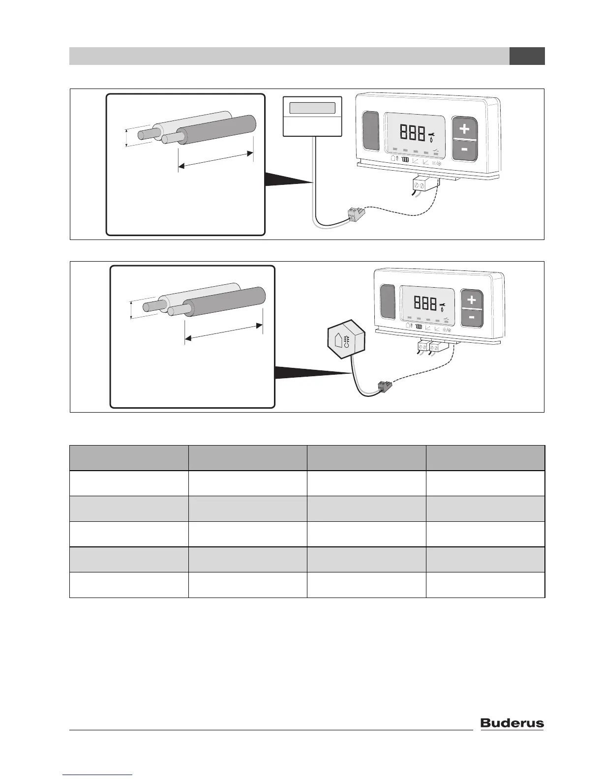
Fig. 2 Thermostat
Fig. 3 Outdoor sensor
On/Off
mode
°F
L
L ≤ 100 ft.
R ≤ 100 Ω
Ø = 18 AWG
Ø
72186100-02N
mode
°F
L
L ≤ 100 ft.
R ≤ 100 Ω
Ø = 18 AWG
Ø
72186100-03N
[°F] [k Ω] [°F] [k Ω] [°F] [k Ω] [°F] [k Ω]
-40 336.5 5 72.9 50 19.9 95 6.5
-31 242.6 14 55.3 59 15.7 104 5.3
-22 177.0 23 42.3 68 12.5 113 4.4
-13 130.4 32 32.7 77 10.0 122 3.6
-4 97.1 41 25.4 86 8.1
Tab. 2 Sensor resistance table