AM10 - We reserve the right to make any changes due to technical modifications!
7
Installation manual
1
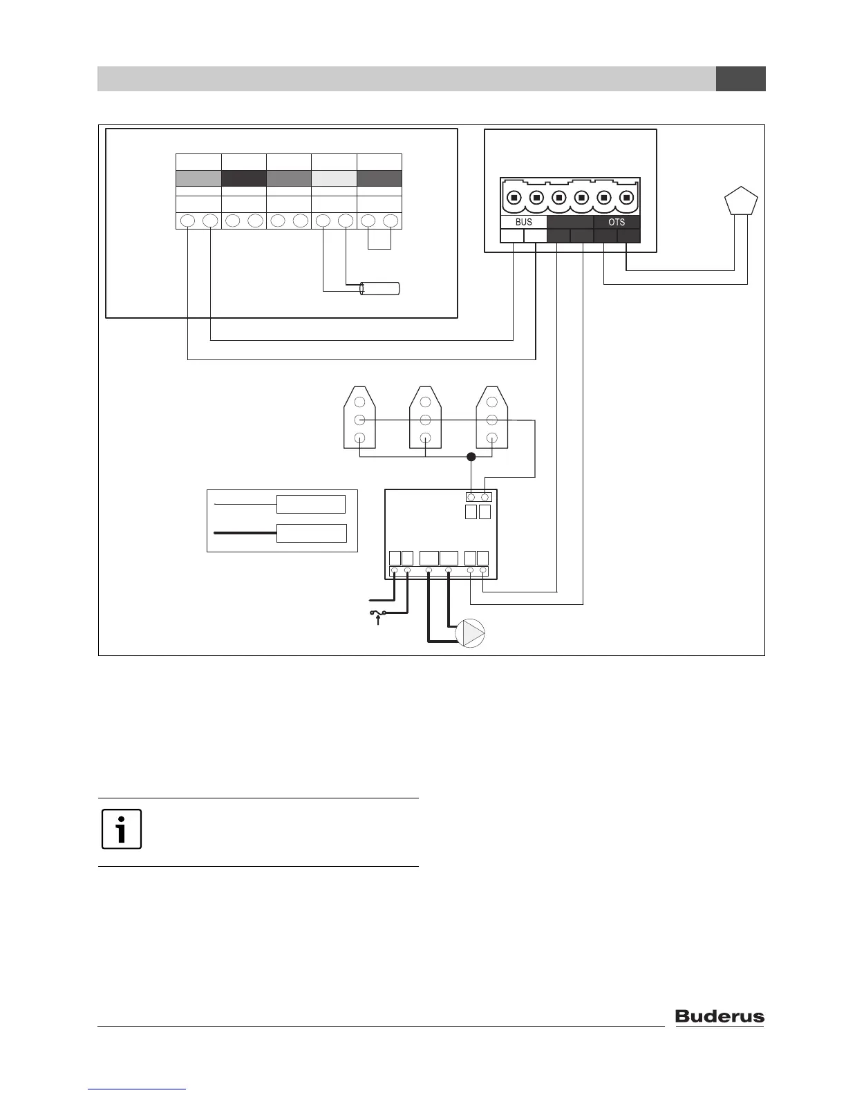
Fig. 5 Wiring detail
If there are multiple zones, wire all
thermostats in parallel for calls for heat
from any thermostat to produce a heat
demand.
Outdoor
sensor
N
Pump Relay
H C1 C2 X X
T T
Dedicated
120 VAC
15 Amp Circuit
Neutral
Zone
valve
Line
120 VAC
Field wiring
Low Voltage
Field wiring
AM10 Module
EV
1
2
FW
1 21 2
WA
1 2
FA
1 2
RC
DHW Tank
Sensor
Factory
Installed
Jumper
RC 10/20
Outdoor
sensor
T T
Connection
DHW
Sensor
Safety
Limit
Orange Blue Lt Green Lt Gray Red
Wire terminal strip
Terminals FA and WA
not used in this
application
1
2
1
2
On / Off
1 2
72186100-05N
Do not install RC10 module
when using this configuration.