Do you have a question about the Buderus GB142 Series and is the answer not in the manual?
Remove the cable plug from the gas control valve for the heat exchanger replacement.
Remove both cable plugs from the fan unit as part of the procedure.
Pull down retaining clips to open and remove the burner cover.
Remove the burner assembly from the appliance.
Disconnect supply and return sensors, noting the marked supply sensor.
Disconnect the safety sensor from the appliance.
Disconnect the hot surface ignitor and ionization electrode plugs.
Loosen fastening screws and dismantle the mounting plate.
Remove the hot surface ignitor and ionization electrode from the heat exchanger.
Open latches on the condensate collector to access components.
Remove the condensate collector from the appliance.
Dismantle the tension spring between the supply pipe and heat exchanger.
Loosen a nut and pull the supply pipe from the heat exchanger.
Pull upwards combustion air supply and flue gas exhaust connections.
Loosen screws and remove the flue gas adapter from the appliance.
Pull the heat exchanger forward and push it upwards.
Remove the flue gas collector and its oval seal from the old heat exchanger.
Apply silicon to both sides of the new oval seal for the flue gas collector.
Reassemble the flue gas collector with the new oval seal to the new heat exchanger.
Install the new seal for the condensate collector and check placement.
Install the new heat exchanger and all other parts in reverse order of disassembly.
| Modulation | Yes |
|---|---|
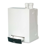
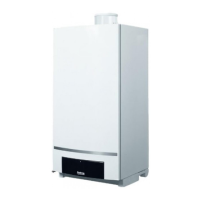
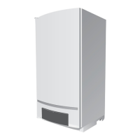
| Installation Type | Wall-mounted |
| Fuel Type | Natural Gas |
| Modulation Ratio | 1:5 |
| Ignition Type | Electronic |