Details of the product
Logamatic SC40 - Specifications subject to change without notice.
6
2
Operating principle
If the set temperature difference between the collector array (Æ Fig. 1, item 1) and the solar cylinder
(Æ Fig. 1, item 3) is exceeded, the pump in the solar pumping station is switched on.
The pump transports the heat transfer medium (the heat transfer fluid) via the circuit through the col-
lector array to the consumer. This consumer is generally a solar storage cylinder. There is a heat
exchanger in the solar storage cylinder. This transfers the heat collected from the sun from the trans-
fer medium to the water intended for domestic use or heating.
If necessary, a hot water mixer unit is fitted to the cylinder to limit the hot water outlet temperature.
Controller
The controller is designed for use with a solar thermal system. It can be mounted on a wall or is inte-
grated in a solar pumping station.
Main components of the solar thermal system
Collector array – Consists of flat plate collectors or evacuated tube collectors
Solar pumping
station
– Consists of the pump together with safety valves and shut-off valves for the
solar thermal circuit
Solar system
cylinder
– Used for storing the collected solar energy
– There are three different types:
– Domestic hot water cylinder
– Reserve cylinder (for heating boost function)
– Combination cylinder (for domestic heating back-up and for domestic hot
water)
Controller
SC40
– Includes two temperature sensors
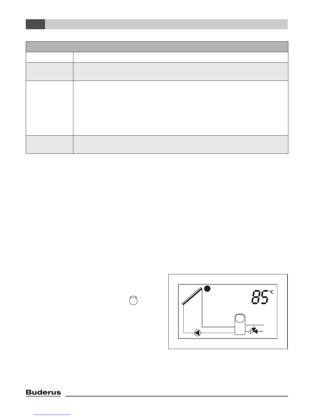
In normal operating mode, the display screen on
the controller stays illuminated in green/yellow for
5 minutes after the last button was pressed (acti-
vated by pressing the rotary selector , for
example).
The display shows the following:
– Pump status (as a simple system diagram)
– System values (e.g. temperatures)
– Selected functions
– Fault messages
Fig. 2 Possible display indications