Logamatic SC40 - Specifications subject to change without notice.
7
Operation
3
3 Operation
Your professional heating technician will set the solar thermal system when commissioning it, and it
will run automatically.
V Have your heating engineer explain to you how the solar thermal system works, and how to oper-
ate it.
V Do not switch off the solar thermal system during long absences (e.g. when going on holiday).
When installed according to the manufacturer's specifications, the solar thermal system is intrin-
sically safe.
V After a power failure or a long absence, check the operating pressure on the pressure gauge of
the solar thermal system (Æ Section 5.4, page 14).
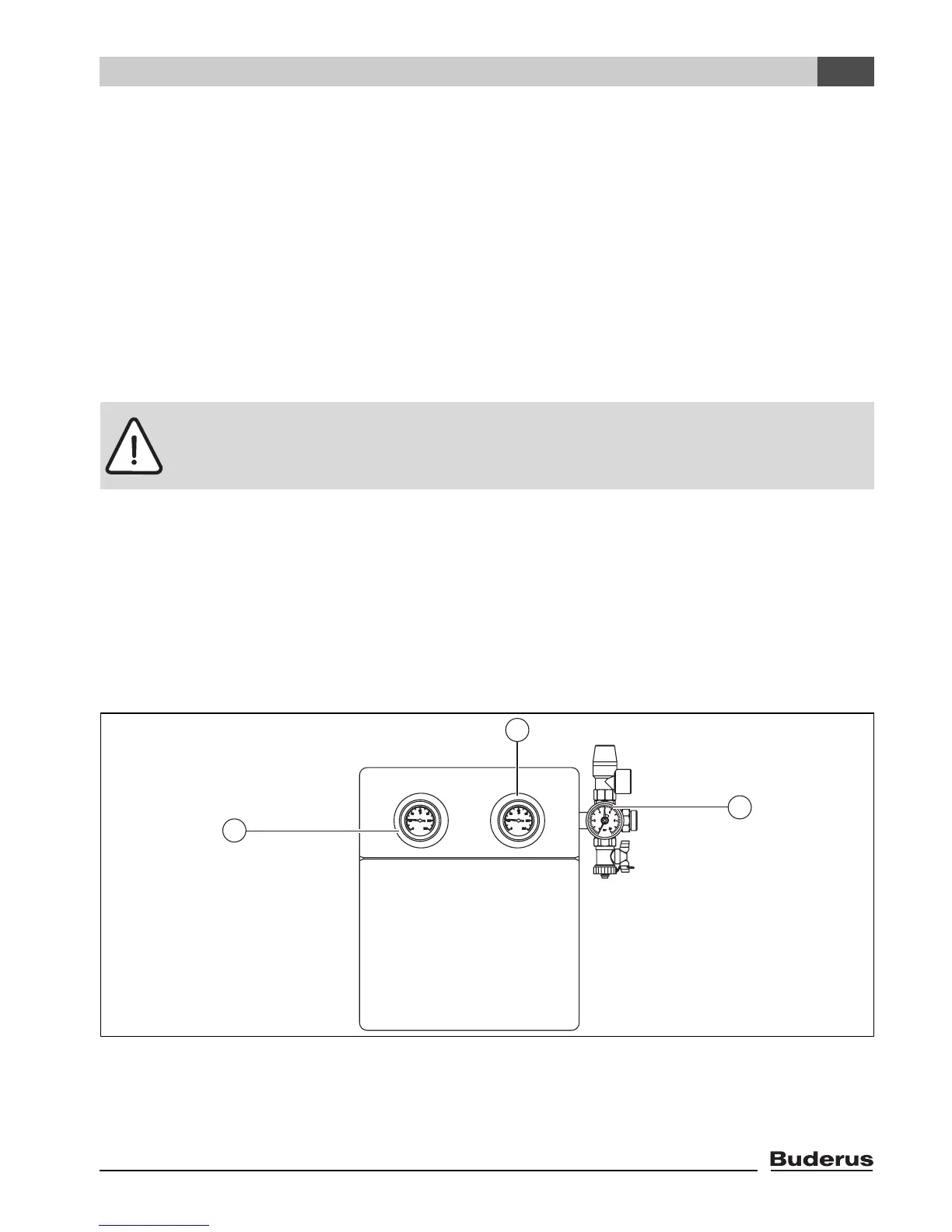
3.1 Elements of the solar pumping station
The main components of the solar pumping station are:
– Thermometers (Æ Fig. 3, items 1 and 3): The built-in thermometers display the temperatures of
the solar return (blue) and flow (red).
– Pressure gauge (Æ Fig. 3, item 2): the pressure gauge indicates the system pressure. The safety
valve above it opens and releases the excess fluid pressure via the blow-off pipe if the system
pressure rises above 6 bar.
Fig. 3 Solar pumping station
1 Display of temperature for solar return
2 Pressure gauge and safety valve
3 Display of temperature for solar flow
Warning: Risk of damage to system if controller settings are changed.
V Do not make any changes to any settings not described here.
7747004985.09-1.SD
1
3
2