Operation
Logamatic SC40 - Specifications subject to change without notice.
8
3
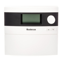
3.2 controller controls
Fig. 4 controller and display
1 Display
2 Rotary selector
3 Back button
4 OK button
5 Symbol for temperature sensor
6 Displays of temperatures, hours of operation, etc.
7 Valve symbol (black = open outlet)
8 Active circulation diagram
Switching off the system
V Disconnect the controller from the mains power supply by means of the isolating device (e.g.
mains plug).
Control Symbol Functions
Rotary selector – Selecting system settings
OK button – Opening submenus and changing settings (engineers only)
Back button – Reverting to collector panel temperature display (View level)
7747006072-23.1 SD
1
2
3
4
5 1 6
78
OK
 Loading...