Home
Buderus
Boiler
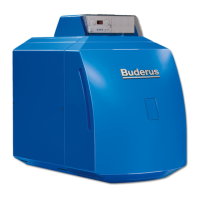
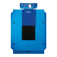
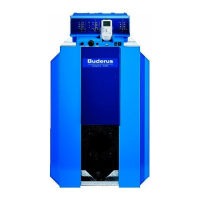
Logano plus GB402
Buderus Logano plus GB402 Installation And Maintenance Instructions For Contractors
4
of 1
of 1 rating
64 pages
Give review
Manual
Specs
To Next Page
To Next Page
Loading...
Read carefully prior to installation and maintenance.
Installation and maintenance instructions for contractors
Gas-fired condensing boiler
Logano plus GB402
6 720 820 700 (2018/01) GB
2
Table of Contents
Default Chapter
2
Table of Contents
2
1 Key to Symbols and Safety Instructions
4
Explanation of Symbols
4
Safety Precautions
4
2 Information on the Device
5
EU Declaration of Conformity
5
Determined Use
5
About These Instructions
5
Tools, Materials and Equipment
5
Product Description
6
Scope of Delivery
7
Dimensions and Specifications
8
Logano Plus GB402 Dimensions
8
Specifications
9
Product Data for Energy Consumption
11
3 Regulations
12
Standards, Regulations and Directives
12
Notes on Installation and Operation
12
Duty to Obtain a Permit and Provide Notification
12
Installation Location
12
Quality of the Heating Water
12
Pipework Quality
12
Frost Protection
12
Combustion Air Connection/Flue Connection
13
Combustion Air Quality
13
Validity of Regulations
13
4 Transporting the Boiler
13
Transporting the Boiler by Crane/Hoist
14
Lifting the Boiler off the Pallet
14
Transporting the Boiler on Rollers
14
5 Installing the Boiler
15
Boiler Room Requirements
15
Wall Clearances
15
Floor-Standing Boiler Levelling
15
6 Fitting
16
Establishing the Flue Gas Connection
16
Installing the Condensate Hose
17
Fitting the Boiler Cover
18
Connecting the Air Supply (for Balanced Flue Operation)
18
Establishing the Heating Circuit Connection
19
Connecting the Flow
19
Installing the Safety Assembly (on Site)
19
Connecting the Return
20
Installing a DHW Cylinder
20
Filling the Heating System and Checking for Leaks
21
Making the Electrical Connection
22
Fitting the Control Unit
22
Establishing the Power Supply Connection
22
Providing the Fuel Supply
23
7 Start up the Heating System
24
Checking the Operating Pressure
24
Checking for Leaks
24
Recording Gas Parameters
25
Check the System Equipment Level
25
Purging the Gas Line
26
Checking the Ventilation and Extract Air Apertures and the Flue Connection
26
Making the Heating System Operational
26
Commissioning the Control Unit and Burner
26
Switching on the Boiler at the BC10
26
Carrying out a Flue Gas Test
26
Accessing the Service Level on the RC35 and Displaying Monitoring Data
27
Measuring the Gas Supply Pressure and Static Pressure
27
Function Tests
30
Checking the Ionisation Current (Flame Current)
30
Check for Water Leaks During Operation
30
Installing Casing Parts
30
Informing the User, Handing over Technical Documents
30
Commissioning Report
31
10 Inspection and Servicing
32
Preparing the Boiler for Inspection
32
General Work
33
Internal Leak Test
33
Determining the Test Volume
33
Carrying out a Leak Test
34
Checking the Heating System Operating Pressure
35
Measuring Carbon Dioxide Content
35
Clean Burner and Heat Exchanger
35
Removing and Cleaning Burner
36
Clean Heat-Exchangers
37
Inspecting the Burner Electrodes
39
Replacing Components
39
Removing the Gas Valve
39
Changing the Gas Filter
40
Removing the Fan
40
Refitting Detached Parts
41
Fitting the Fan
41
Fitting the Ventilation Air Collector and the Gas Valve
41
Fitting the Burner
41
Fitting the Gas Line to the Gas Valve
42
Fitting the Ventilation Air Unit
42
Check for Water Leaks During Operation
42
Checking the Ionisation Current
42
Completing Inspection and Maintenance
42
1Removing Meters
42
2Installing Casing Parts
42
3Checking the Gas/Air Ratio
42
4Confirming Inspection and Maintenance
42
Replacing the Gaskets Subject to Time in Use
42
Inspection and Maintenance Reports
43
8 Shutting down the Heating System
32
Shutting down the Heating System Via the Control Unit
32
Shutting down the Heating System in an Emergency
32
9 Environment / Disposal
32
11 Troubleshooting
46
Recognising the Operating Condition and Clearing Faults
46
Emergency Mode
46
Operating and Fault Displays
47
Operating Messages of the Controller
47
Control Unit Fault Displays
48
Status Indicator of the Burner Control Unit
55
12 Appendix
56
Sensor Curves
56
Temperature Sensor at the Burner Control Unit
56
Hydraulic Resistance
56
Connecting Diagram MC10
56
Safe Connection Diagram
59
Burner Setting
60
Keyword Index
61
Other manuals for Buderus Logano plus GB402
Operating Instructions
20 pages
Installation And Maintenance Instructions
76 pages
4
Based on 1 rating
Ask a question
Give review
Questions and Answers:
Need help?
Do you have a question about the Buderus Logano plus GB402 and is the answer not in the manual?
Ask a question
Buderus Logano plus GB402 Specifications
General
Type
Condensing boiler
NOx class
5
Permissible operating overpressure
3 bar
Fuel type
Natural gas
Dimensions (HxWxD)
600 x 600 x 600 mm
Related product manuals
Buderus Logano plus GB402 Series
12 pages
Buderus Logano plus GB312
16 pages
Buderus Logano plus GB102S
12 pages
Buderus Logano GB125
16 pages
Buderus Logano GB125 BE
64 pages
Buderus Logano GB125 BE US
12 pages
Buderus Logano G315
8 pages
Buderus Logano GE515
16 pages
Buderus Logano GE615
80 pages
Buderus Logano G115 WS
8 pages
Buderus Logano G115/4 WS
60 pages
Buderus Logano G124X II/SP
12 pages