6 720 808 905 (2014/04) MP100
8 |
Product details
▶The product requires different voltages.
Do not connect the extra-low voltage side to the mains
voltage or vice versa.
▶ Also observe connection diagrams of other system
components.
Handover to the end user
When handing over the heating system, explain the operating
conditions to the user.
▶ Explain how to operate the heating system, with particular
emphasis on all safety-related actions.
▶ Explain that conversions or maintenance must only be
carried out by a competent person.
▶ Point out the need for inspections and maintenance for
safe and environmentally friendly operation.
▶ The installation and operating instructions must be given to
the end user for keeping.
Damage caused by frost
The system can freeze if it is switched off:
▶ Observe the notices regarding frost protection.
▶ Due to the additional functions, e.g. DHW heating or anti-
seizing protection, the system should always be left on.
▶ Correct any faults immediately.
2 Product details
• The module serves to activate a swimming pool connected
to a heat pump with a EMS plus interface.
• The module serves to determine the swimming pool
temperature and activate a mixer as required by the heat
pump.
• Anti-seizing function: the connected mixing valve actuator
is monitored and run automatically for a short period after
24 hours of downtime. This prevents the mixer from
seizing up.
A maximum of one MP100 is permitted in a system,
irrespective of the number of other BUS nodes.
2.1 Standard delivery
Fig. 1, page 77:
[1] Module
[2] Bag with installation accessories
[3] Swimming pool temperature sensor TC1 installation set
[4] Installation instructions
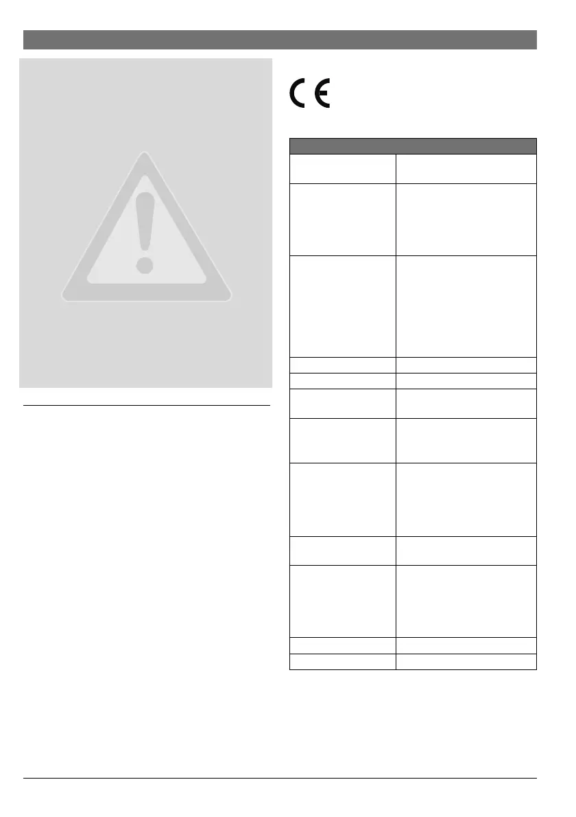
2.2 Technical data
Design and operation of this product conform to
European Directives and the supplementary
national requirements. Its conformity is
demonstrated by the CE marking .
Technical data
Measurements
(W × H × D)
151 × 184 × 61 mm (further
dimensions Fig. 2, page 77)
Maximum conductor
cross-section
• 230 V terminal
•Extra-low voltage
terminal
•2.5mm
2
•1.5mm
2
Rated voltages
•BUS
• Module power supply
•User interface
•Mixer
• 15 V DC (reverse-polarity-
protected)
• 230 V AC, 50 Hz
• 15 V DC (reverse-polarity-
protected)
• 230 V AC, 50 Hz
Circuit breaker 230 V, 5 AT
BUS interface EMS plus
Power consumption on
– standby
<1W
Maximum output
• Per connection
(VC1) • 100 W
Temperature sensor
capturing range
• lower fault limit
•display range
• upper fault limit
•<– 10°C
• 0 ... 100 °C
•>125°C
Permissible ambient
temperature
0 ... 60 °C
IP rating
• For installation in
heat source
• For wall-mounted
installation
• Determined by the IP rating of
the heat appliance
•IP44
Protection class I
ID no. Data plate ( Fig. 15, page 82)
Table 2
 Loading...