2002 Buell X1: Engine 3-39
HOME
CLEANING AND INSPECTION
1. Clean all parts in cleaning solvent. Blow out holes and oil
passages with compressed air.
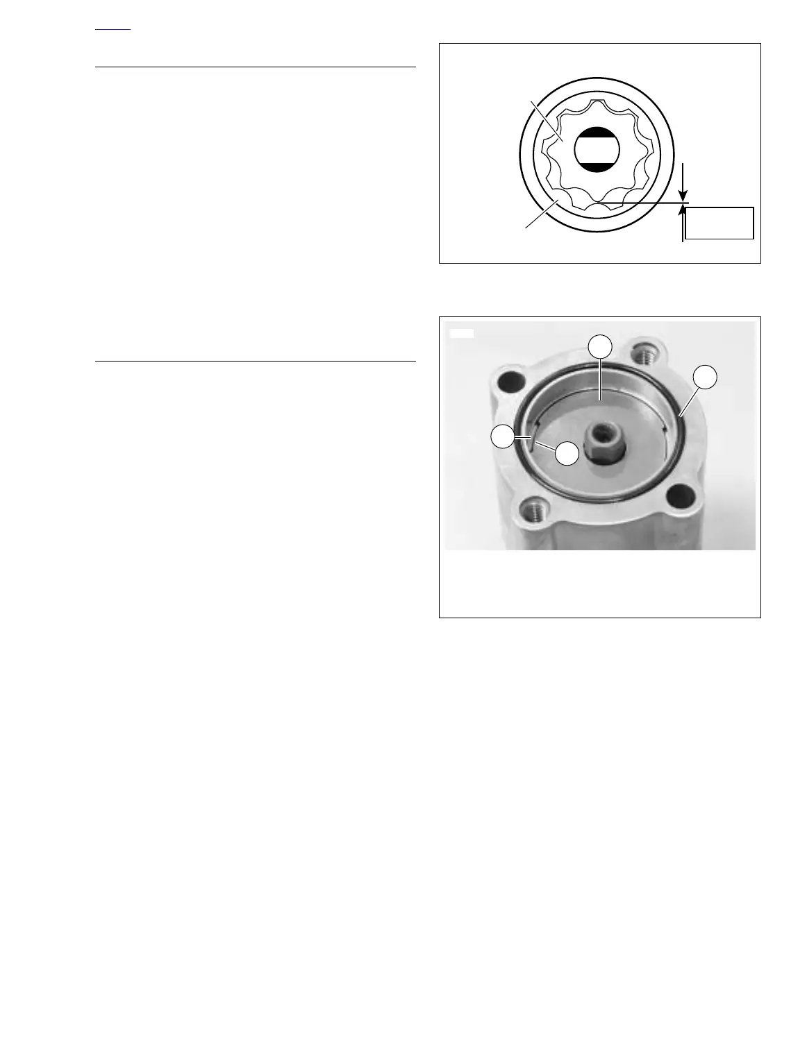
2. See Figure 3-56. Inspect both gerotor sets for wear.
a. Mesh pieces of each set together as shown.
b. Use a feeler gauge to determine clearance.
c. The SERVICE WEAR LIMIT between gerotors is
0.004 in. (0.102 mm). Replace gerotors as a set if
clearance exceeds this dimension.
d. Measure thickness of feed gerotors with a microme-
ter. Replace gerotors as a set if they are not the
same thickness.
3. See Figure 3-55. Check gear shaft (11) teeth for damage
or wear. Replace if necessary.
ASSEMBLY/INSTALLATION
NOTE
Liberally coat all moving parts with clean engine oil to ensure
easy assembly and smooth operation at start-up.
1. See Figure 3-55. Install gear shaft (11) through body
(12). Position thrust washer (15) over end of shaft. Install
new
retaining ring (16) into groove in shaft.
2. Insert inner gerotor of the gerotor scavenge set (9) over
gear shaft.
3. Place outer gerotor over inner gerotor to complete scav-
enge set (9).
4. See Figure 3-57. Install gerotor separator plate (1) by lin-
ing up slots (2) on perimeter with tabs (3) inside oil pump
body.
5. Install a
new
O-ring (4) into groove in pump body.
6. See Figure 3-55. Place gerotor feed set (7) over gear
shaft (11).
7. Place cover onto pump body. Install cover TORX screws
(2). Tighten screws to 70-80
in-lbs
(8-9 Nm).
8. Place
new
mounting gasket (10) in position.
NOTE
Use
new
hose clamps. If fittings were removed, use
TEFLON
®
PIPE SEALANT or HYLOMAR
®
on fitting threads.
9. See Figure 3-54. Attach return hose connection (4).
10. Secure pump to crankcase with mounting screws (1) and
washers. Tighten screws to 125-150
in-lbs
(14-17 Nm).
11. Attach feed hose (3) and oil filter hose connection (5).
12. Attach clamp (6) and canister to hose.
13. Check engine oil level. Add oil to correct level if needed.
See 1.6 ENGINE LUBRICATION SYSTEM.
Figure 3-56. Gerotor Wear Limits
Figure 3-57. Separator Plate Slots
Inner Gerotor
b0097x3x
Outer Gerotor
Wear
Limit
0.004 in.
(0.102 mm)
1
6620
2
3
1. Gerotor Separator Plate
2. Slot on Separator Plate
3. Tab on Oil Pump Body
4. O-Ring
4