4
INITIAL SET-UP
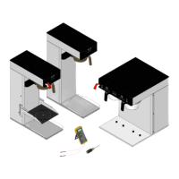
1. Apply the four non-skid pads from the parts box to the bottom of the legs.
2. Remove the drip tray assembly, drip tray bracket, and splash panel assembly from the parts box.
3. Place a set of key holes in the drip tray bracket over the lower two screws in the panel below the hopper
access door; push down gently and tighten screws.
4. Place the set of key holes in the splash panel over the upper two screws and position so the screws are
between the holes.
ELECTRICAL REQUIREMENTS
CAUTION - The dispenser must be disconnected from the power source until specified in Electrical Hook-Up.
The 120 volt version of this dispenser has an attached cordset. The mating connector must be a NEMA
5-15R.
To access terminal block for high voltage models without a cordset, remove left side panel.
Electrical Hook-Up
CAUTION - Improper electrical installation will damage electronic components.
1. An electrician must provide electrical service as specified.
2. Using a voltmeter, check the voltage and color coding of each conductor at the electrical source.
3. Place the ON/OFF/NIGHT switch in the “ON” position.
4. Connect the dispenser to the power source.
5. If plumbing is to be hooked up later be sure the dispenser is disconnected from the power source. If
plumbing has been hooked up, the dispenser is ready for Initial Fill & Heat.
CE REQUIREMENTS
• Thisappliancemustbeinstalledinlocationswhereitcanbeoverseenbytrainedpersonnel.
• Forproperoperation,thisappliancemustbeinstalledwherethetemperatureisbetween0°Cto35°C.
• Applianceshallnotbetiltedmorethan10°forsafeoperation.
• Anelectricianmustprovideelectricalserviceasspeciedinconformancewithalllocalandnationalcodes
• Thisappliancemustnotbecleanedbywaterjet
• Thisapplianceisnotintendedforusebypersons(includingchildren)withreducedphysical,sensoryor
mental capabilities, or lack of experience and knowledge, unless they have been given instructions concern-
ing use of this appliance by a person responsible for its safety.
37510 090407

 Loading...