c) 100 volts ac for two wire 100 volt models.
I
SERVICE (cant .)
Indicator Lamp(s)
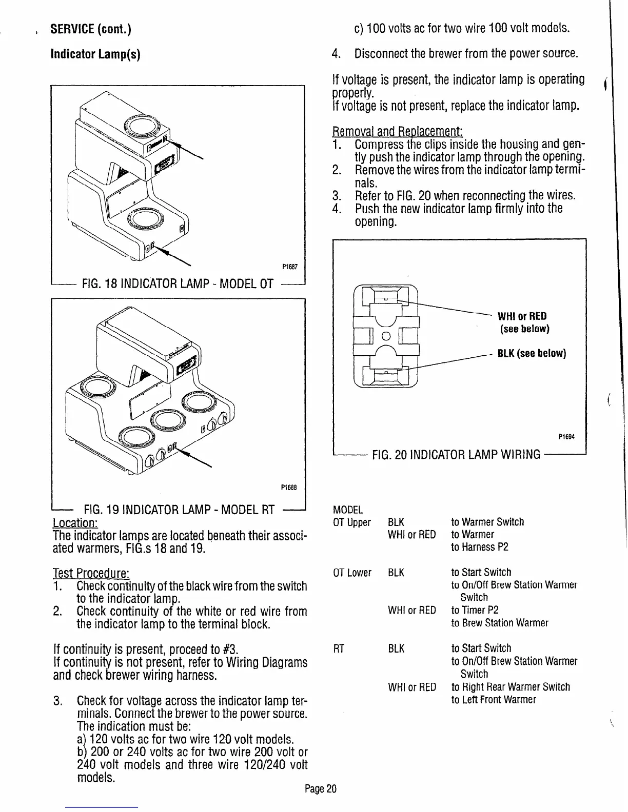
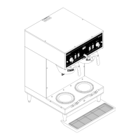
- FIG. 18 INDICATOR LAMP -
MODEL
P1687
OT -
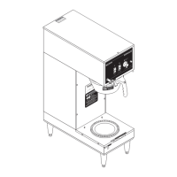
P1688
- FIG. 19 INDICATOR LAMP - MODEL RT -
Location:
The indicator lamps are located beneath their associ-
ated warmers, FlG.s 18 and 19.
MODEL
OT Upper
BLK
to Warmer Switch
WHI or RED to Warmer
to Harness P2
Test Procedure:
OT Lower BLK
to Start Switch
1. Check continuity of the black wire from the switch
to On/Off Brew Station Warmer
to the indicator lamp.
Switch
2. Check continuity of the white or red wire from
WHI or RED to Timer P2
the indicator lamp to the terminal block.
to Brew Station Warmer
If continuity is present, proceed to #3.
If continuity is not present, refer to Wiring Diagrams
and check brewer wiring harness.
3. Check for voltage across the indicator lamp ter-
minals. Connect the brewer to the power source.
The indication must be:
a) 120 volts ac for two wire 120 volt models.
b) 200 or 240 volts ac for two wire 200 volt or
240 volt models and three wire 120/240 volt
models.
RT BLK
to Start Switch
to On/Off Brew Station Warmer
Switch
WHI or RED to Right Rear Warmer Switch
to Left Front Warmer
4. Disconnect the brewer from the power source.
If voltage is present, the indicator lamp is operating
properly.
i
If voltage is not present, replace the indicator lamp.
Removal and Replacement:
1. Compress the clips inside the housing
and
gen-
tly push the indicator lamp through the opening.
2. Remove the wires from the indicator lamp termi-
nals.
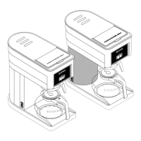
3. Refer to FIG. 20 when reconnecting the wires
4. Push the new indicator lamp firmly into the
opening.
WHI or RED
(see below)
BLK (see below)
PI694
- FIG. 20 INDICATOR LAMP WIRING
Page 20