EasyManua.ls Logo

Bunn ULTRA-2 PAF User Manual

Bunn ULTRA-2 PAF
4 pages
To Next Page IconTo Next Page
Page #1 background imageLoading...
Page #1 background image
8. Wash components in a mild
solution of dish detergent using
a bristle brush. Rinse and dry
each item thoroughly before
reassembling.
NOTE: Parts must be thoroughly
dry before adding powder to the
hopper.
7. Slip the O-ring off the Whip-
per Chamber Receptacle and
remove the shaft seal.
4. Twist the Whipper Chamber
clockwise and pull it off the
Whipper Chamber Receptacle.
5. Pull the Frother off the Motor
Shaft. Notice the flat keyway on
the shaft and the matching key-
way inside the Frother. It is im-
portant that these two keyways
are lined up when reassembling.
6. Twist Whipper Chamber Re-
ceptacle clockwise and pull it off
the Motor Shaft. Wipe down all
inside surfaces.
USE & CARE INSTRUCTIONS for ULTRA-2 COLD DRINK DISPENSER WITH PAF DISPENSER
NOTICE - This guide is for quick reference only and is not intended to replace the information in the Operation Manual!
DISASSEMBLY & CLEANING
EMPTY ALL PRODUCT FROM THE ULTRA HOPPERS INTO A BUCKET OR CONTAINER BEFORE PROCEEDING!
1. Open the Cabinet Door and
allow the support arms to lock
in place. Door must remain
open during the entire cleaning
procedure.
3. Pull the Mixing Chamber out
of the Whipper Chamber.
BUNN-O-MATIC CORPORATION
POST OFFICE BOX 3227
SPRINGFIELD, ILLINOIS 62708-3227
PHONE: (217) 529-6601 FAX: (217) 529-6644
43553.0000A 07/10 ©2010 Bunn-O-Matic Corporation
ULTRA-2 PAF
ULTRA-2 PAFA
(Page 1 of 4, Continued)
2. Place the power switch in
the OFF position. Slide the gate
shut on the powder hopper and
remove the hopper. Wipe the
hopper tray clean of powder
residue.
Question and Answer IconNeed help?

Do you have a question about the Bunn ULTRA-2 PAF and is the answer not in the manual?

Bunn ULTRA-2 PAF Specifications

General IconGeneral
ManufacturerBunn
ModelULTRA-2 PAF
CategoryBeverage Dispenser
Hopper Capacity3 gallons per hopper
Number of Hoppers2
Amperage12 amps
Refrigeration SystemAir Cooled
Electrical120V / 60Hz

Summary

Disassembly and Cleaning Procedures

Cabinet Door Support Arms

Ensure cabinet door support arms lock in place during cleaning.

Power Switch and Hopper Removal

Turn off power, shut powder hopper gate, and remove hopper.

Mixing Chamber Extraction

Pull the mixing chamber out of the whipper chamber.

Whipper Chamber Detachment

Twist and remove the whipper chamber from its receptacle.

Frother Removal and Keyway Alignment

Remove frother from motor shaft, noting keyway alignment for reassembly.

Whipper Chamber Receptacle Removal

Remove whipper chamber receptacle by twisting it clockwise.

O-ring and Shaft Seal Removal

Remove O-ring and shaft seal from the whipper chamber receptacle.

Component Washing and Drying

Wash parts in detergent solution, rinse, and dry thoroughly.

Disassembly and Cleaning Steps

PAF Assembly and Hopper Lock

Slide PAF assembly back until it latches before removing Ultra Hoppers.

Hopper Lock Plunger and Lift

Depress the hopper lock plunger and lift slightly.

Hopper Assembly Forward and Remove

Pull the hopper assembly forward and remove it.

Auger Removal from Cooling Drum

Pull the auger from the cooling drum.

Hopper Seal Removal

Remove the hopper seal from the flange on the cooling drum.

Faucet Valve Caution

Handle faucet valve carefully due to spring tension to prevent damage.

Spring and Faucet Seal Removal

Carefully slide valve up to remove spring and faucet seal.

Auger Nose Bushing Removal

Remove auger nose bushing, avoiding scratches on the surface.

Drip Tray and Cover Removal

Remove the drip tray and cover.

Part Soaking and Washing

Soak and wash all parts in hot water and sanitizer solution.

Surface Cleaning and Sanitizing

Clean external surfaces with a wash cloth dampened in hot water and sanitizer.

Rinsing and Drying

Thoroughly rinse all surfaces and wipe dry before reassembly.

Assembly Procedures

Auger Nose Bushing Installation

Replace the auger nose bushing inside the front of the hopper.

Hopper Seal Installation

Install the hopper seal over the flange at the rear of the cooling drum.

Auger Shaft Alignment

Align auger shafts and rotate them for proper keyway alignment.

Hopper Installation

Install hopper over auger and cooling drum, ensuring lock plunger snaps.

Faucet Seal and Spring Position

Position the faucet seal and return spring in the faucet valve.

Faucet Valve Assembly

Slide the faucet valve assembly into place on the hopper.

Faucet Handle Installation

Press down on valve, position handle, and snap into place.

Drip Tray and Cover Installation

Install the drip tray and cover.

Function Settings and Product Mixing

Turn on functions and mix product thoroughly before adding to hoppers.

PAF Assembly and Final Reassembly

Slide PAF assembly forward, reassemble all parts, and power on.

Thorough Cleaning of PAF Hopper

Cabinet Door and Support Arms

Open cabinet door and allow support arms to lock in place.

Hopper Gate and Cover Removal

Slide gate shut, remove hopper, cover, and empty contents.

Ejector Elbow and Slide Gate Removal

Remove Ejector Elbow and Slide Gate from the Hopper Base.

Wiper Blade, Drive Gear, and Auger Removal

Remove Wiper Blade, Drive Gear, and Auger from the Hopper Base.

Auger Drive Shaft Removal

Remove Auger Drive Shaft by turning the screw clockwise.

Component Washing and Drying

Wash all components in detergent solution, rinse, and dry thoroughly.
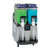
Related product manuals