36
SERVICE (cont.)
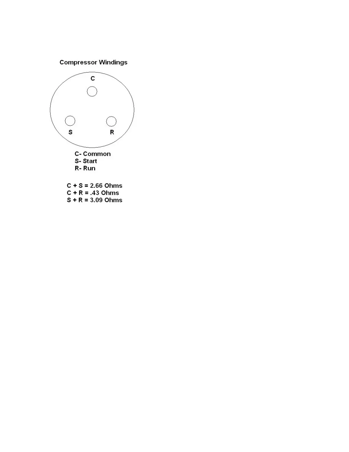
COMPRESSOR (EMBRACO) (ULTRA-2)
Compressor Windings & Related Component Testing:
Note: Measure the resistance (ohms) between termi-
nal pins C&S and C&R around ambient temperature
of 77° F. Add the resistance between C & S and C & R.
The sum should equal the resistance found between S
& R. A 10% deviation is acceptable.
Continuity must be present between C & S and C & R.
If there is no continuity on start or run winding, there
is an interruption within that winding.
Check the C (common) compressor winding to com-
pressor ground terminal/housing. If continuity is
present, one of the compressor windings is shorted
to ground.
Check Compressor Windings for Ground Fault:
Upon removal of the protective terminal cover, if evi-
dence is shown by any lead or terminal being over-
heated, it is a good indication that a compressor wind-
ing problem may exist. Follow the recommended step
below to check the compressor winding insulation. If
a ground fault is detected with the compressor, keep
the power off, thermal protector and potential relay
disconnected. A licensed certified refrigerant techni-
cian will need to replace a defective compressor.
Testing Compressor Windings/Insulation with a Meg-
ger
A megger is a preferred test over using a typical ohm
meter for testing the compressor windings. The meg-
ger checks the insulation factor of a winding making
sure it is actually insulated and not leaking current
(Ground Fault). An ohm meter usually produce a low
voltage for reading resistance verses a megger uses
higher direct voltage source to measure insulation re-
sistance to detect a breakdown in the motor winding
insulation.
Step 1: Disconnect all electrical power to the BUNN
ULTRA-2 HP.
Step 2: Access compressor terminal pins and discon-
nect the wire leads going to the compressor pins.
Step 3: Set the megger to the compressor applicable
voltage rating. If the megger you are using only has
a few specific voltage ranges, select the next highest
voltage above your compressor volt range.
Step 4: Connect one lead of the megger to the copper
suction line or housing. Connect the other lead to one
of the compressor terminal pins (winding).
Step 5: Repeat the procedure for the two remaining
terminal pins. If the instrument indicates any resis-
tance less than 2 megohms between any pin and the
housing (copper suction line), a ground fault exists.
Replace compressor.

 Loading...