17
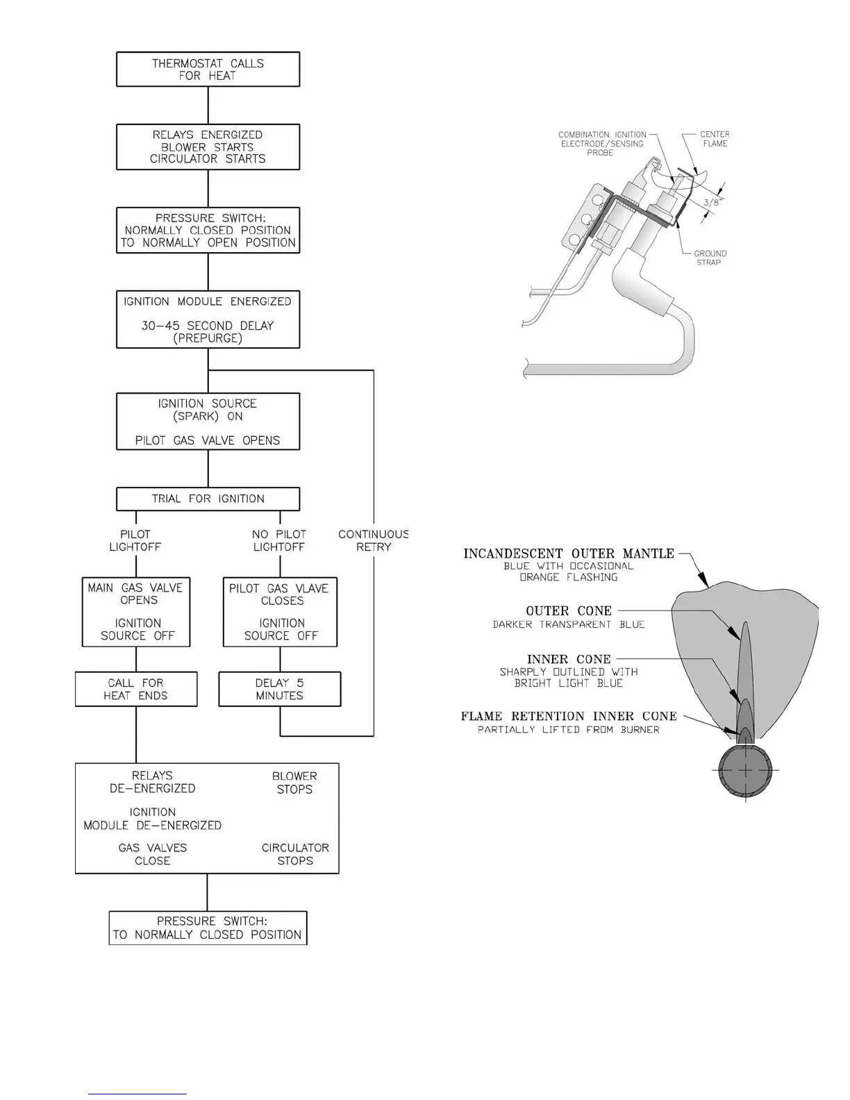
Figure 15: Pilot Burner Flame
Figure 14: Sequence of Operation
H. Check pilot burner fl ame. See Figure 15. Flame
should be steady, medium hard blue enveloping 3/8 to
½ inch of sensing probe.
I. Check main burner fl ame. See Figure 16. Flame
should have clearly defi ned inner cone with no yellow
tipping. Orange-yellow streaks should not be confused
with true yellow tipping.
Figure 16: Main Burner Flame
J. Check thermostat operation. Raise and lower
temperature setting to start and stop boiler operation.
K. Check ignition control module shut-off. Disconnect
igniter/sensor cable from Terminal 9 (SPARK). Gas
valve should close and pilot and main burners should
extinguish.
 Loading...


