25
Table 7: Pilot Burner Location
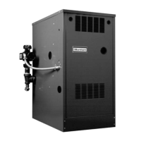
Figure 18: Spark Gap Setting
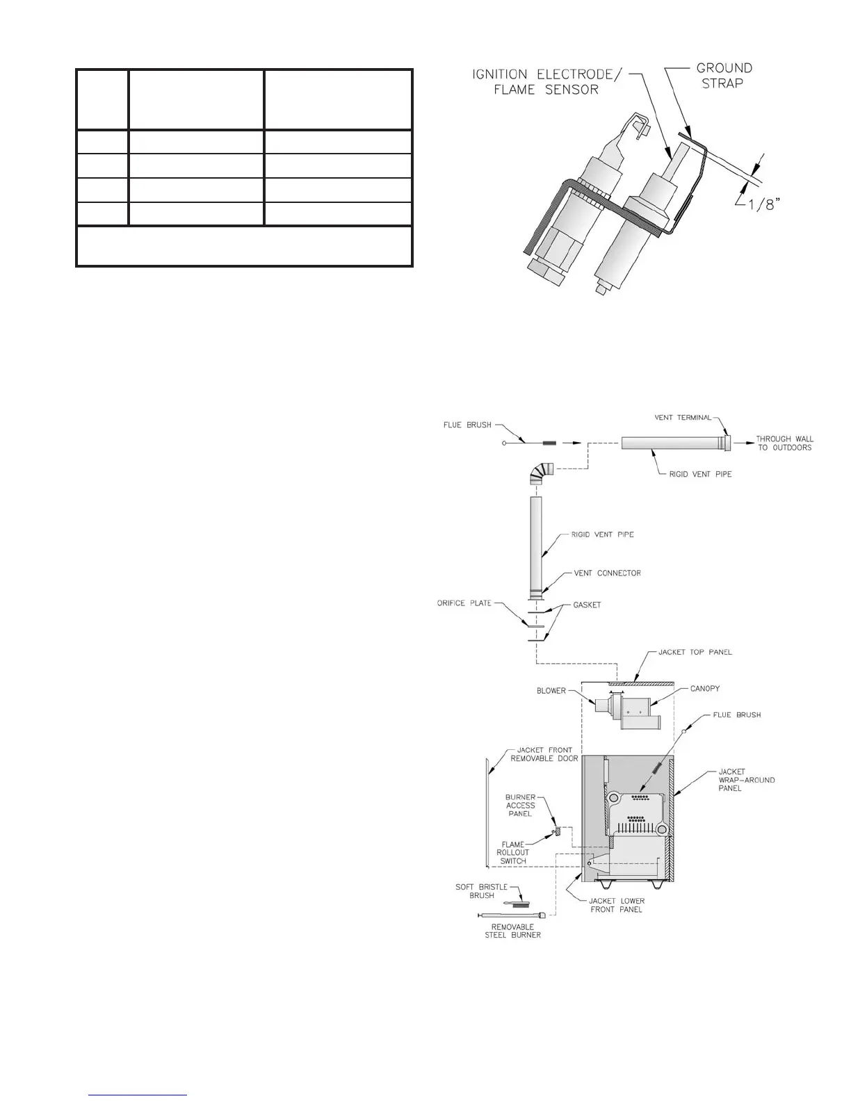
Figure 19: Flueway Cleaning
H. Removal or replacement of pilot assembly or
pilot assembly parts. If pilot assembly, sensor or
pilot orifi ce need replacing, remove main burner
with pilot using procedure described in
Paragraph F.1.
1. To replace orifi ce.
a. Disconnect pilot tubing. Pilot orifi ces
screw into Pilot Burner. Replace with
Honeywell 388146NE (Natural Gas) or
Honeywell 388146KP (LP/Propane).
b. Reconnect pilot tubing and check for
leaks.
2. To adjust or check spark gap between
electrode and hood on Honeywell Q348A
intermittent pilot. See Figure 18.
a. Use round wire gauge to check spark
gap.
b. Spark gap should be 1/8 inch for
optimum performance.
3. To replace complete pilot assembly.
a. Remove two machine screws holding
pilot burner to pilot bracket.
b. Disconnect pilot tubing.
c. Disconnect all other leads to pilot.
d. Select pilot assembly with identical
model number, reconnect leads and pilot
tubing. Resecure to pilot bracket.
4. Reinstall main burner following procedure
described in Paragraph F.
I. Lubrication. There are no parts requiring
lubrication by service technician or owner.
Circulator bearings are water lubricated. Blower
motor bearings are factory sealed.
J. Procedure for measuring blower inlet
pressure. See Figure 20.
1. With boiler off, remove hose at pressure
switch.
2. With tee connect water manometer as shown
with additional tubing.
relioB
ledoM
htiwrenruBniaM
*tekcarBtoliP°06
detacoLrenruBtoliP
niaMneewteB
*srenruB
VP3021 2&1
VP4022 3&2
VP5023 4&3
VP6024 5&4
morfdeweivsathgirottfelderebmunsrenrubniaM*
.reliobfotnorf
 Loading...


