9
Table 2: Maximum Capacity of Schedule 40 Pipe in CFH For Gas Pressures of 0.5 psig or Less
Table 3: Fitting Equivalent Lengths
Table 4: Specifi c Gravity Correction Factors
htgneL
]teeF[
porDerusserP.c.whcni3.0 porDerusserP.c.whcni5.0
½¾ 1 ¼1½¾1¼1
01231872025050,1571063086004,1
0229091053037021052564059
033725158209579002573077
043603154200528071023066
056551151204437151582085
060550159100466831062035
07646908107316521042094
08340907105375811022064
09044806102335011502034
001839705150305301591004
gnittiF
eziSepiPlanimoN
½¾ 1 ¼1
llE°547.012.16.1
llE°096.11.26.25.3
)woblEsA(eeT1.31.42.59.6
cificepS
ytivarG
noitcerroC
rotcaF
cificepS
ytivarG
noitcerroC
rotcaF
05.001.103.170.1
55.040.104.140.1
06.000.105.100.1
56.069.006.179.0
07.039.007.149.0
57.009.0
08.078.0
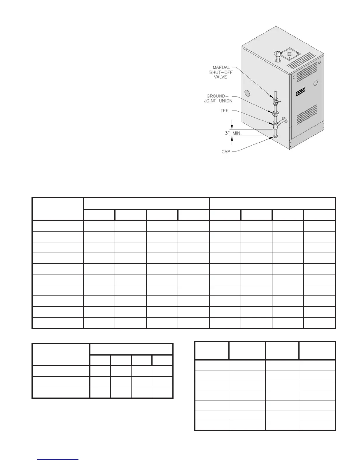
Figure 6: Recommended Gas Piping
3. Install sediment trap, ground-joint union and manual
shut-off valve upstream of boiler gas control valve
and outside jacket. See Figure 6.
4. All above ground gas piping upstream from manual
shut-off valve must be electrically continuous and
bonded to a grounding electrode. Do not use gas
piping as grounding electrode. Refer to National
Electrical Code, ANSI/NFPA 70 and/or CSA C22
Electrical Code.
C. Pressure test. The boiler and its gas connection must
be leak tested before placing boiler in operation.
1. Protect boiler gas control valve. For all testing over
½ psig, boiler and its individual shut-off valve must
be disconnected from gas supply piping. For testing
at ½ psig or less, isolate boiler from gas supply
piping by closing boiler's individual manual shut-off
valve.
2. Locate leaks using approved combustible gas
detector, soap and water, or similar nonfl ammable
solution. Do not use matches, candles, open fl ames,
or other ignition source.
 Loading...