From the run mode, press
ENTER
to get access to the programming mode (the display
shows -Pro-). Press two times the
key to go to the entry stage of the display
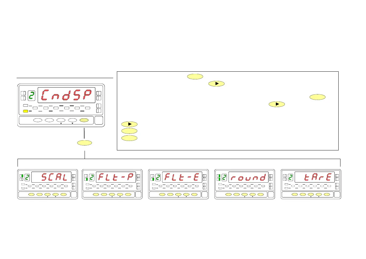
configuration module, represented in fig. 18.1. This module provides five menus :
scaling, balanced filter, damping filter, round and tare (lockout). Press
ENTER
to
access to the first menu (SCAL) and press repeatedly the
key if you want to
shift around the different menus (See next pages for instructions on each menu).
Go to next programming module.
ENTER
Enter the selected menu.
ESC
Go to run mode.
18
3./ Display range programming.
After deciding the values for INPUT and DISPLAY and the decimal point position, we are ready to enter in the display configuration
module (2 CndSP) to efectively scale the meter. The scaling procedure is completed with digital filters and display rounding.
[18.1] Display configuration
B
TARE
HOLD LIMI T MAX MIN DATA
DSP2INP2 FL
STORE
DSP1
INP1
2
1
4
3
TARE
RESET LIMIT MAX/MIN ENTE
ESC
DATA
PROG
TEACH
PRG
RUN
TARE
HOLD LIMI T MA
MIN DAT
DSP2INP
FL
STORE
DSP1
INP1
1
4
3
TARE
RESET LI M I T MAX/ MI N ENTER
ES
DAT
PROG
TEACH
PR
RUN
TARE
HOLD LIMI T MA
MIN DAT
DSP2INP
FL
STORE
DSP1
INP1
1
4
3
TARE
RESET LI M I T MAX/ MI N ENTER
ES
DAT
PROG
TEACH
PR
RUN
TARE
HOLD LIMI T MA
MIN DAT
DSP2INP
FL
STORE
DSP1
INP1
1
4
3
TARE
RESET LI M I T MAX/ MI N ENTER
ES
DAT
PROG
TEACH
PR
RUN
TARE
HOLD LIMI T MA
MIN DAT
DSP2INP
FL
STORE
DSP1
INP1
1
4
3
TARE
RESET LI M I T MAX/ MI N ENTER
ES
DAT
PROG
TEACH
PR
RUN
TARE
HOL
LIMI T MA
MIN DAT
DSP
INP
FL
STORE
DSP1
INP1
1
4
3
TARE
RESET LI MI T M AX/ M I N ENTER
ES
DAT
PROG
TEACH
PR
RUN
MENU 2A
SCALE
MENU 2B
BALANCED FILTER
MENU 2B
DAMPING FILTER
MENU 2AB
ROUND FILTER
MENU 2
TARE
ENTER
Optionally, the model 9181 can incorporate one or several
output options for communications (this output should
never be connected to the telephone lines) or control
including :
COMMUNICATION
RS2 Serial RS232C
RS4 Serial RS485
CONTROL
ANA Analogue 4-20 mA, 0-10 V
2RE 2 SPDT relays 8 A
4RE 4 SPST relays 0.5 A
4OP 4 open-collector NPN outputs
4OP 4 open-collector PNP outputs
All options are optoisolated with respect to the input signal and
supplied with their instructions manual where you can find the
characteristics, installation and programming.
he output cards are easily installed on the meter's main board
by means of plug-in connectors and each one activates its own
programming module that provides complete software-
configuration.
.
Additional capabilities of the unit with output options :
•
Control and processing of limit values via ON/OFF logic
outputs (2 relays, 4 relays, 4 NPN outputs or 4 PNP
outputs) or proportional output (4-20 mA or 0-10 V).
•
Communication, data transmission and remote programm-
ing via serial interface.
For more detailed information on characteristics, applications,
mounting and programming, please refer to the specific
manual supplied with each option.
4. OUTPUT OPTIONS
38
 Loading...