PACKAGE CONTENTS
Instructions manual in English including Declaration of
Conformity.
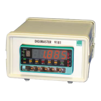
D.P.M. model 9181
Accessories for panel mounting (sealing gasket and
fastening clips).
Accessories for wiring connections (removable plug-in
connectors and fingertip).
Wiring label sticked to the 9181
Set of engineering units labels
• Check the package contents.
CONFIGURATION
Power supply (pages 9 and 10)
Instruments supplied for 115/ 230 V AC power are factory
set for 230 V AC (USA market 115 V AC).
Instruments supplied for 24/ 48 V AC power are factory
set for 24 V AC.
Instruments supplied for 10-30 V DC can be powered
from any voltage between 10 and 30 V DC without need
of making changes.
• Check the wiring label before power connection.
2. GETTING STARTED
8
Programming instructions (Pages 11 and 12)
he software is divided into several independently
accessible modules for configuration the input, the display,
the setpoints, the analog output, the output
communication and logic inputs.
9 Read carefully this section.
Input type and connections (Pages 13, 14, 15 and 16)
The instrument provides four excitation voltages to supply
the transducer 2,2V, 5V , 10V or 24V, are set up at
factory for 10V.
9 Check the transducer sensitivity, if you have any doubt
please consult the transducer specifications
.
Programming Lock-out (page 35)
• The instrument is set at the factory with thelock-out code
to “0000”.
Warning!
9 Note and keep in safe place de lock-out code.
28
TARE. A push of this key adds the current display value to
the tare memory and brings the display to zero. The "TARE"
LED indicates that a tare value different from zero is
contained in the tare memory.
o reset the tare memory press and hold down the "RESET"
key, then press the "TARE" key. Release first "TARE" then
"RESE
". To take a tare or reset it back to zero, be sure
these functions are enabled by software (see Fig. 27.2, TARE
menu, UnLoCK option).
3.1 – KEYBOARD FUNCTIONS
The front-panel keyboard includes the following function keys: TARE, RESET, LIMIT and MAX/MIN. The functionality of each
one, which is avaliable in the "RUN" mode is described next.
TAR
HOL
LIMIT MAX MI
DAT
DSP2INP2 FL
STORE
DSP1
INP1
1
4
3
TARE
RESET L I MI T MAX/ MI
ENT E
ES
DAT
PROG
TEAC
PR
RUN
[28.1] Tare operation
TAR
HOL
LIMIT MAX MI
DAT
DSP2INP2 FL
STORE
DSP1
INP1
1
4
3
TARE
RESET L I MI T MAX/ MI
ENT E
ES
DAT
PROG
TEAC
PR
RUN
[28.2] Tare reset
LIMIT. During the RUN mode, this key is only operative in
case that the instrument incorporates one of the following
output options : 2 relays (ref. 2RE), 4 relays (ref. 4RE), 4
NPN transistors (ref. 4OP) or 4 PNP transistors (ref. 4OPP).
At one push of "LIMIT" key the display illuminates the "limit"
LED and reads the first programmed setpoint value with the
LED 1 activated. New strokes on the LIMIT key recalls
successively the rest of the setpoints with the corresponding
LED (on the right) activated.
The setpoint values are shown at each push of the "LIMIT"
key independently of whether they are enabled or inhibited.
15 seconds after the last key operation or by a push of
"LIMIT" from the visualitation of the last setpoint, the meter
returns to the normal reading.
3. KEYBOARD AND REMO
E CONTROLS
[28.3] Setpoint 1 value
TAR
HOL
LIMIT MAX MI
DAT
DSP2INP2 FL
STORE
DSP1
INP1
1
4
3
TARE
RESET L I MI T MAX/ MI
ENT E
ES
DAT
PROG
TEAC
PR
RUN