EasyManua.ls Logo

Burster 9181 User Manual

Burster 9181
55 pages
To Next Page IconTo Next Page
Page #1 background imageLoading...
Page #1 background image
T
he previously programmed INP3 value appears on the display, LED INP2 activated.
There are two methods to program input values :
Key-in method: Use
to switch between "0" (positive) and "-" (negative).
Press
to advance to the next digit to the right which goes in flash. Press
repeatedly
to increment the active digit until it takes desired value. Proceed in
the same manner with all the digits until desired value is completed on the display
with sign. Press
ENTER
to accept this value as INP3 and go next step.
Teach method: Apply signal to the meter input. Press
TEACH
to view the actual
signal value present at the input connector, LED INP2 flashes. Press
ENTER
to accept
this value as INP3 and go next step.
ESC
To exit from the programming mode
Programming of the display value for the third point, activated LED DSP2. By means of
the
and procedure, program desired DSP3 value and press
ENTER
. The
limits of the span are -9999 and 9999 points.
a) To validate data and advance to the next point ; press
ENTER
; or
b)
T
o save the programmed data in the memory and return to the run mode (the
meter is scaled by three points), press and hold down
ENTER
for 3 seconds.
ESC
To exit from the programming mode without saving changes.
MULTIFUNCTION DIGITAL PANEL
METER
FAST ADQUISITION
MODEL 9181
MODBUS-RTU PROTOCOL COMPATIBLE
INSTRUCTIONS MANUAL
Code: 30727148
Edition: October 2001
Valid for models with software version M-1
21
[21.2] Input 3 value
B
A
TARE
HOLD LIMIT MA
X
MIN DATA
DSP2INP2 FL
T
STORE
DSP1
INP1
2
1
4
3
TARE
RESET LIMIT MAX/MIN ENTE
R
ES
C
DATA
PROG
TEACH
PR
G
RUN
[21.3] Display 3 value
B
A
TARE
HOLD LIMIT MA
X
MIN DATA
DSP2INP2 FL
T
STORE
DSP1
INP1
2
1
4
3
TARE
RESET LIMIT MAX/MIN ENTE
R
ES
C
DATA
PROG
TEACH
PR
G
RUN
1 second flag indication for scaling point 3.
Multi-slope scaling sequence begins at this step..
[21.1] Point 3
B
A
TARE
HOLD LIMIT MA
X
MIN DATA
DSP2INP2 FL
T
STORE
DSP1
INP1
2
1
4
3
TARE
RESET LIMIT MAX/MIN ENTE
R
ES
C
DATA
PROG
TEACH
PR
G
RUN
DIGIMASTER
Question and Answer IconNeed help?

Do you have a question about the Burster 9181 and is the answer not in the manual?

Burster 9181 Specifications

General IconGeneral
BrandBurster
Model9181
CategoryMeasuring Instruments
LanguageEnglish

Summary

Digimaster Introduction

Custom Configuration

Allows quick and easy configuration via front panel keys and menus.

Instrument Calibration

Recommended recalibration at periodical intervals according to ISO9001 standards.

Model 9181 Overview

Model 9181 Overview

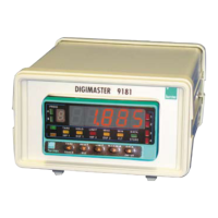
General overview of the Model 9181.

Getting Started

Information on initial setup and basic operations.

Keyboard and Connector Controls

Details on front panel controls and connectors.

Output Options

Information on available output interfaces.

Technical Specifications

Key technical data and parameters of the instrument.

Warranty Information

Warranty terms and conditions.

Declaration of Conformity

Compliance with relevant standards and directives.

Input Configuration

Input Configuration Access

Accessing the input programming module.

Input Type Selection

Selecting the input signal type (mV, V, mA, Pot).

Display Configuration

Display Range Configuration

Scaling the instrument using input/display points.

Action Modes

Explains forward and reverse operation modes.

Display Range Programming

Display Configuration Access

Accessing the display configuration menus.

Menu 2A: Scale

Scale Configuration

Accessing the scale configuration menu.

Input 1 Value Programming

Programming the first input value.

Display 1 Value Programming

Programming the first display value.

Menu 2B: Balanced Filter

Balanced Filter Access

Accessing the balanced filter menu.

Balanced Filter Value Setting

Setting the balanced filter level (0-9).

Menu 2B: Damping Filter

Damping Filter Access

Accessing the damping filter menu.

Damping Filter Value Setting

Setting the damping filter level (0-9).

Menu 2AB: Round Filter

Round Filter Access

Accessing the round level selection.

Rounding Increment Selection

Selecting the rounding increment for display stabilization.

Menu 2: Tare Function

Tare Menu Access

Accessing the tare function menu.

Tare Lock/Unlock and Reset

Enabling/disabling and resetting the tare function.

Keyboard Functions in Run Mode

Tare Operation

Performing a tare operation by pressing the TARE key.

Tare Reset

Resetting the tare memory using RESET and TARE keys.

Setpoint 1 Value Display

Displaying the first programmed setpoint value.

Max/Min Value Functions

Peak Value Display

Recalls the maximum value and activates the MAX LED.

Valley Value Display

Recalls the minimum value and activates the MIN LED.

Peak Value Memory Reset

Erasing peak, valley, and peak-peak memories.

Programming Logic Inputs

Logic Inputs Access

Accessing the logic input configuration menus.

Menu 6A: PIN 1 Programming

PIN 1 Menu Access

Accessing the PIN 1 configuration menu.

Function Number Selection for PIN 1

Selecting the logic function number for a pin.

Additional Functions

Setpoint Functions

Setpoint value programming and new functions.

RS232 Communication

ModBus-RTU protocol compatibility.

RS485 Communication

Printer communication and ModBus-RTU compatibility.

Analog Output Reference

Reference to connector functions for analog output.

Sample & Hold Function

Function to hold values during quick phenomena.

Setpoint Option Index

Setpoint Option Particularities

Specific details about the setpoint option.

Menu 3B for Setpoints

Configuration menu for setpoint parameters.

Direct Setpoint Value Programming

How to directly modify setpoint values.

Output Reaction Time

Time taken for output response.

Related product manuals