For input process signal mA
9181
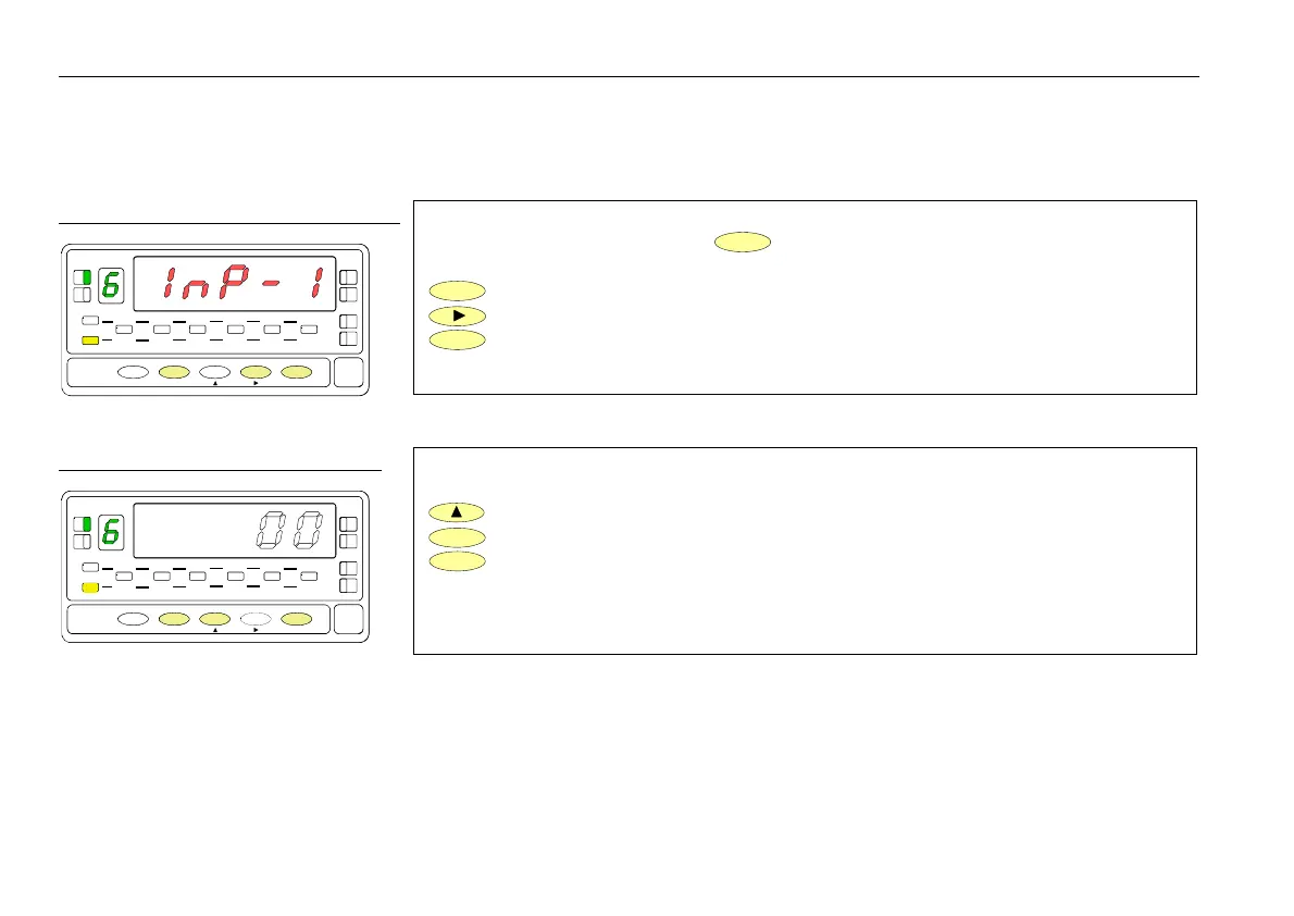
The figure 36.1 shows the indication (InP-1) corresponding to the configuration menu
for the PIN 1 function. Press the
ENTER
key to acceed this configuration.
ENTER
To acceed to the programming of the PIN 1 function.
To skip over this menu and go to PIN 2.
ESC
To exit from the programming mode without saving changes.
Choose the function number [0-31], according to the table.
To change number (hold down to increment automatically).
ENTER
To save the entry into the memory and return to the run mode.
ESC
To exit from the programming mode without saving changes.
Excitation selection jumpers
fig. 16.1
16
Exc = 24V DC not stabilized J3
Exc = 2,2V DC not adjustable J4
Exc = 5V DC J5 + J2 P1 = fine adjust 5V
Exc = 10V DC J5 + J1 P2 = fine adjust 10V
Default setting Exc=10V
P2 adjust 10V.
P1 adjust 5V.
WARNING! J3, J4, J5 connect only one
P1
Connection type potentiometer with
Input impedance > 10MΩ
POT.
Excitation = 2.2V Jumper J4
Input type = Potentiometer
36
MENU 6A - PIN 1 programming
his menu allows selecting the logic function for PIN 1. Available functions are represented by a number from 0 to 31. Consult
tables to find the number corresponding to the desired function. The instructions given below apply to pin function 1. Follow the
same procedure to configure the rest of the pins.
[34.1] Menu PIN 1
TARE
HOLD LIMIT MAX MIN DATA
DSP2INP2 FL
STORE
DSP1
INP1
1
4
3
TARE
RESET LIMI T MAX/ MIN ENTER
ESC
DATA
PROG
TEACH
PRG
RUN
[34.2] Function numbe
TARE
HOLD LIMIT MAX MIN DATA
DSP2INP2 FL
STORE
DSP1
INP1
1
4
3
TARE
RESET LIMI T MAX/ MIN ENTER
ESC
DATA
PROG
TEACH
PRG
RUN
Transducer excitation selection
 Loading...