11
Connect the instrument to the main supply. During a few
seconds al segments will turn on as a checking of the good
function of the device.
Press
ENTER
key to enter to the programming mode and the
display will show the indication -Pro-.
he programming rutine is divided in independant access
modules, accessible by pressing the
key from the level
–pro- in this order:
1. CnInP =Input configuration.
2. CndSP =Display configuration.
3. SetP =Setpoints.
4. Anout =Analog output.
5. rSout = Serial output.
6. LoGIn =Logical input.
The 3, 4 and 5 modules will be omitted if the 2RE option,
analog option or serial option are not installed.
he
information about the programming of each one is explained
in its manuals.
he picture shows how to enter in the programming mode,
the module selection level and the exit saving changes or not
saving changes. Once the display shows the indication of the
module, the access to the configuration menus is done by
pressing
ENTER
key.
The
ESC
key exits the programming mode from any
programming step.
he global diagrams, that can be seen in the picture, shown
the way to advance in the programming of the instrument
2.2
Programming instructions
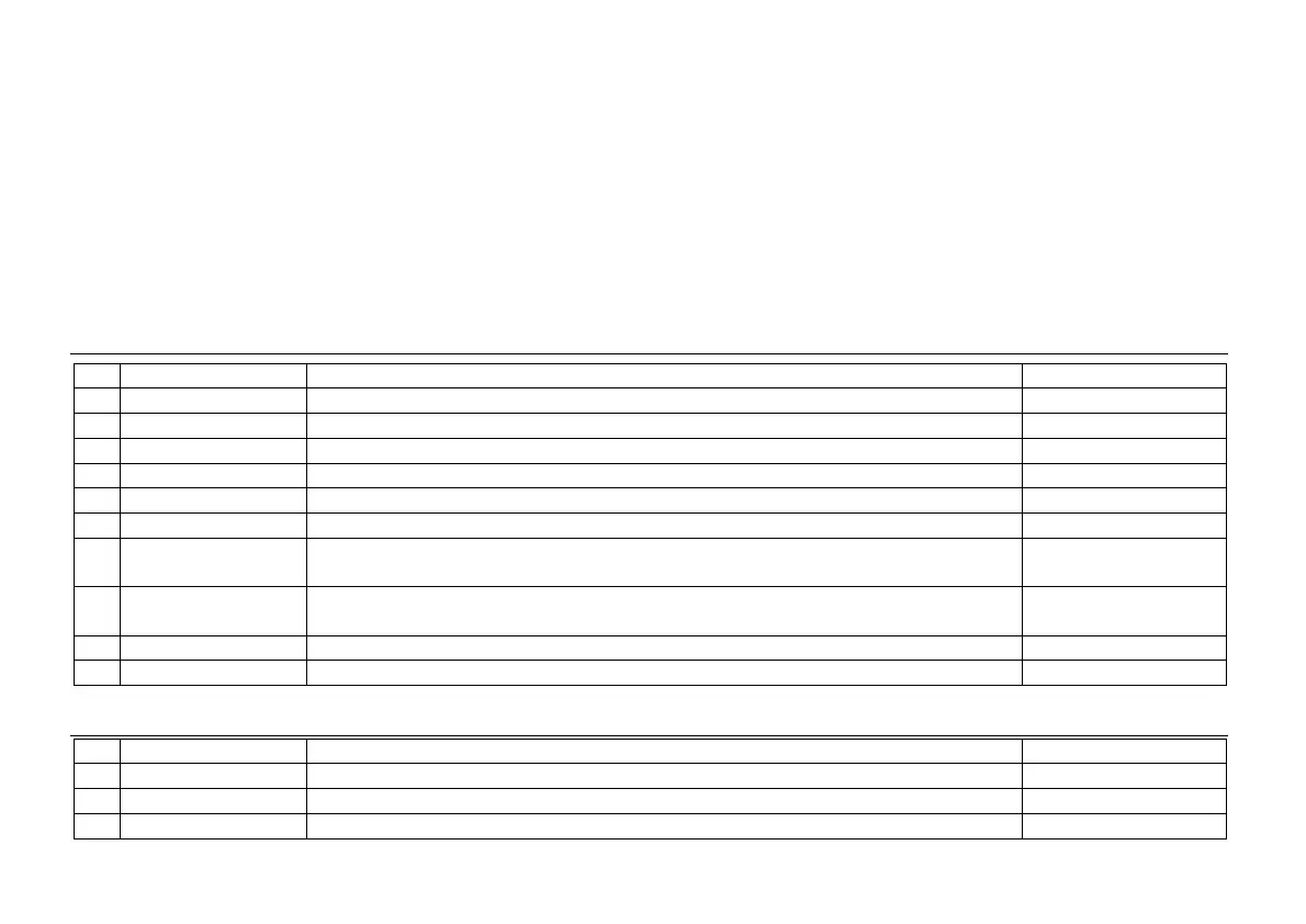
3.3 - Table of programmable functions
• Nº : Function number.
• Function : Function name.
• Description : Description and characteristics of the function.
• Activation :
• Falling edge : The operation is performed on a falling edge applied to the pin with respect to COMMON.
• Low level : The function remains activated while the corresponding pin is held at a low level with respect to COMMON.
- (*) Default factory configuration. It can be restored by programming all pins to '0'.
• (1) Activating the functions 3 and 4 simultaneously the peak-peak value is shown.
Nr Function Description Activation
0 Deactivated None None
1 TARE (*) Adds the current display value to the tare memory. The display goes to zero Pulse
2 RESET TARE Adds the tare memory contents to the display value and clears the tare memory Pulse
3 PEAK (1) Display PEAK value. Fixed level
4 VALLEY (1) Display VALLEY value. Fixed level
5
RESET PEAK/VALLEY
Clears the peak or valley memory (if the values are on display) Pulse
6 PEAK/VALLEY (*) 1
st
push recalls peak, 2
nd
push recalls valley, 3
rd
push recalls peak-peak, 4th
push brings the meter to the indication of the variable being measured
Pulse
7 RESET (*) Combined with (1) delete the tare.
Combined with (6) delete peak or valley.
Pulse combined with (1)
or (6)
8 HOLD1 Holds the display while the outputs remain active Fixed level
9 HOLD2 (*) Holds the display, the RS and the analog outputs Fixed level
0 to 9 : DISPLAY / MEMORY FUNCTIONS
10 to 12 : FUNCTIONS ASSOCIATED WITH THE DISPLAY OF THE INPUT VARIABLE
Nº Function Description Activation
10 INPUT Displays the actual input signal value in mV (flashing) Fixed level
11 GROSS Displays the measured value + the tare value = gross Fixed level
12 TARE Displays the amount of tare contained in the memory Fixed level
31
 Loading...