The figure 24.1 shows the indication (FLt-P) corresponding to entry stage of the
balanced filter menu. Press the
ENTER
key to acceed this menu.
ENTER
To access to the programming filter.
To skip over this menu and go to next one.
ESC
To exit from the programming mode without saving changes.
4
he balanced filter acts as a delay on the display response to signal variations produced at the input. The effect of incrementing
this filter level results in a softer response of the display to the input variations.
The filtering level is programmable from 0 to 9. Level 0 disables the filter.
MENU 2B - BALANCED FILTE
24
[24.1] Balanced filte
The figure 24.2 shows the initially selected level for the filter-P (any number between
0 and 9) with the FLT LED activated.
Press repeatedly the key to change the digit until desired value appears on the
display.
ENTER
To save the entry into the memory and go to the next programming menu.
ESC
To exit from the programming mode without saving changes.
[24.2] Filter value
B
TARE
HOLD LIMIT MA
MIN DATA
DSP2INP2 FL
STORE
DSP1
INP1
2
1
4
3
TARE
RESET LIMIT MAX/MIN ENTE
ES
DATA
PROG
TEACH
PR
RUN
B
TARE
HOLD LIMIT MA
MIN DATA
DSP2INP2 FL
STORE
DSP1
INP1
2
1
4
3
TARE
RESET LIMIT MAX/MIN ENTE
ES
DATA
PROG
TEACH
PR
RUN
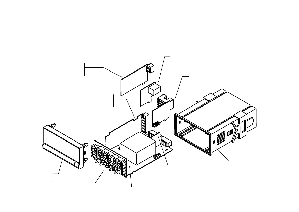
ANALOG OUTPUT
BOARD
INPUT
BOARD
RS232C or RS485
OUTPUT BOARD
SETPOINTS
OUTPUT BOARD
POWER
FILTER CIRCUIT
CASE WITH
FIXING CLIPS
MAIN BOARD
FRONT-PANEL
COVER
DISPLAY