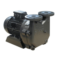
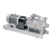
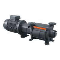
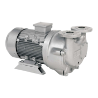
The Busch Dolphin LX 0030-0430 A is a series of vacuum pumps designed for industrial use, operating on the fluid ring principle. These pumps are suitable for the suction of non-explosive gases and vapours and are thermally suitable for continuous operation (100 percent duty). They are not ultimate pressure proof, and operation with a closed (blanked) suction line will damage the vacuum pump.
Function Description
At a standstill, the pump housing (g) should be filled with an operating liquid (usually water) to approximately the shaft centerline. Upon starting, the impeller (h) throws the liquid to the periphery of the housing, forming a rotating liquid ring that seals the space between the impeller and the housing. In the 12 o'clock position, the liquid ring touches the hub of the impeller. As the impeller rotates counterclockwise (view from the non-drive end), the liquid ring moves away from the hub, creating space for gas to be drawn in through the intake port (e) (approximately from the 11 o'clock to the 8 o'clock position). The chamber surrounded by the hub, the liquid ring, and two adjacent impeller blades achieves its maximum volume in the 6 o'clock position. As the impeller continues to rotate, the liquid ring moves closer to the impeller hub, the volume of the chamber decreases, and the enclosed gas is expelled through the discharge port (f) (approximately from the 3 o'clock position to the 12 o'clock position). This sequence repeats for every chamber between two impeller blades with each revolution. The operating liquid also absorbs the heat of compression and condensation when conveying saturated media. The control of the level and temperature of the operating liquid are essential for satisfactory operation.
The vacuum pump is cooled by the airflow from the fan wheel of the drive motor, the process gas, and the operating liquid. The pump comes without start controls; these must be provided during installation.
Important Technical Specifications
The Dolphin LX series includes models from LX 0030 A to LX 0430 A, with varying nominal motor ratings, volume flow, sound pressure levels, and dry weights.
- Frequency: Available in 50 Hz and 60 Hz.
- Nominal Motor Rating: Ranges from 0.75 kW (LX 0030 A, 50 Hz) to 15 kW (LX 0430 A, 60 Hz).
- Speed: Ranges from 1450 min⁻¹ to 3500 min⁻¹.
- Volume Flow: Ranges from 24 m³/h (LX 0030 A, 50 Hz) to 430 m³/h (LX 0430 A, 60 Hz).
- Sound Pressure Level (EN ISO 2151): Ranges from ~25 dB(A) to ~198 dB(A).
- Dry Weight: Ranges from 70 kg to 72 kg.
- Max. Gas Inlet Temperature: 80 °C.
- Max. Discharge Pressure: 2 bar (a).
- Once Through Operating Liquid Requirement: Ranges from 3 L/min (LX 0030 A) to 30 L/min (LX 0430 A). This average flow for once-through operation can be reduced by 50% for partial recovery.
- Max. Service Liquid Temperature: 40 °C.
- Ultimate Pressure: 33 hPa abs (= mbar abs).
The operating liquid supply system can be configured in three basic models: once-through cooling (no recovery), partial recovery, and closed-loop/total recovery. All arrangements include a source of operating liquid, a regulating device, a means of stopping flow when the pump is shut off, and a means of separating the gas-liquid exhaust mixture.
Usage Features
- Installation Prerequisites: The vacuum pump must be installed in a non-potentially explosive environment, complying with ambient temperatures of 5-40 °C and atmospheric pressure. It must be placed or mounted horizontally on an even base, with a minimum clearance of 0.1 m from nearby walls for sufficient cooling. Heat-sensitive parts should not touch the pump's surface, and the installation space must be vented.
- Suction Connection: The suction line must fit the suction connection (a) and have a line size at least as large as the connection. For lines exceeding 2 m, larger sizes are prudent to avoid efficiency loss and overload. A manual or automatic operated valve should be provided in the suction line if vacuum is to be maintained after shutdown. The suction line must be free of foreign objects.
- Gas Discharge: The discharge piping should not exceed an elevation of 600 mm above the discharge flange (c) until the liquid is separated, to prevent back pressure and drive motor overload. The discharged gas must flow without obstruction. The discharge line should fit the gas discharge (c) and have a line size at least as large as the connection. For lines exceeding 2 m, larger sizes are prudent. The discharge line should slope away from the vacuum pump or include a liquid separator/drip leg to prevent liquid backup.
- Electrical Connection: Electrical installation must be performed by qualified personnel according to relevant regulations (IEC, CENELEC, DIN VDE, BGV A2). The drive motor's power supply must be compatible with its nameplate data, and an overload protection (EN 60204-1) must be provided. The pump's drive should not be affected by electrical or electromagnetic disturbances. For mobile installations, electrical connections should have strain relief.
- Direction of Rotation: For three-phase motors, the intended direction of rotation is indicated by an arrow. The pump housing (g) must be filled with operating liquid to the shaft centerline before starting to prevent the mechanical seal from running dry. The fan wheel's rotation direction should be checked by "bumping" the motor. If the rotation needs to be changed, any two of the drive motor wires (three-phase motor) must be switched.
- Operating Liquid: Water is typically used, but other ring liquids may be used with Busch's consent. The kinematic viscosity at operating temperature should not exceed 2 mm²/s, and the vapour pressure should not exceed 16 mbar. Condensation upstream of the pump (jet or surface condenser) is preferred to avoid cavitation. The operating liquid level should reach the middle of the shaft only when starting the pump.
- Pressure Control: To prevent cavitation, the working pressure should be sufficiently above the operating liquid's vapour pressure. Pressure control in the vacuum system must not be achieved by throttling or closing the suction line. A vacuum relief valve is the most effective measure to limit inlet pressure.
- Contamination: In closed operating liquid circuits, softened water should be used. No dirt particles larger than 0.1 mm should enter the vacuum pump via process gas or operating liquid. Filters should be used to remove larger dirt particles. The dirt concentration should not exceed 5 volume percent.
Maintenance Features
- Safety: Prior to any contact, the vacuum pump must be shut down and locked against inadvertent start-up. During operation, the surface can reach temperatures over 70 °C, posing a burn risk. Cooling down or heat protection gloves are required for contact. All covers, guards, and hoods must remain mounted, and protective devices must not be disabled. Cooling air inlets and outlets must not be covered or obstructed.
- Contaminated Filters: If the pump conveys gas contaminated with hazardous materials, filters may contain harmful substances. Personal protective equipment must be worn when handling contaminated filters, which are special waste and must be disposed of separately according to regulations.
- Monthly Maintenance:
- Check for abnormal audible noise (rumble, click/knock, mechanical seal squealing).
- Check for excessive vibration (should be less than 5.5 mm/s RMS).
- Check operating liquid temperature (consult order documentation).
- Check bearing temperature (should not exceed 60 °C with water or 80 °C with oil at 25 °C ambient).
- Check if the vacuum pump achieves the specified vacuum level.
- Check all pipework for leakage, especially mechanical seals.
- Every 6 Months: Clean the housing from dust and dirt if necessary.
- Every Year: If an inlet screen is installed, check and clean it.
- Dismantling and Reassembly: Complete disassembly is rarely needed. The end casing (106.7) can be removed, and the inspection cover (704.3) allows inspection/replacement of the valve plate flap (742.1) without full strip-down. All parts must be thoroughly cleaned before reassembly. The valve plate flap must be secured with the retainer, covering all holes in the end casing. Gasket sealant should be used between joints.
- Overhaul: Busch service requires a legally binding "Declaration of Contamination" for any vacuum pump submitted for overhaul.
- Removal from Service: Before disconnecting pipes/lines, ensure they are vented to atmospheric pressure. If water is used as operating fluid and ambient temperatures may fall below 0 °C, or if the pump is shut down for over 12 weeks, the water must be drained. If water is not drained, ensure it contains sufficient antifreeze.
- Dismantling and Disposal: Materials and components treated as special waste must be separated. The vacuum pump should be disposed of as scrap metal, ensuring it is not contaminated with harmful foreign material.
- Troubleshooting: The manual provides a comprehensive troubleshooting guide for common issues such as the pump not reaching usual pressure, drawing too high current, taking too long to evacuate, not starting, or running noisily, along with possible causes and remedies.