EasyManua.ls Logo

Bush A626N User Manual

Bush A626N
143 pages
To Next Page IconTo Next Page
Page #1 background imageLoading...
Page #1 background image
26&32LCD TV Bush A626N&A632N
1
Service
Service
Service
Table of Contents
Description Page Description Page
SAFETY NOTICE
ANY PERSON ATTEMPTING TO SERVICE THIS CHASSIS MUST FAMILIARIZE HIMSELF WITH THE CHASSIS
AND BE AWARE OF THE NECESSARY SAFETY PRECAUTIONS TO BE USED WHEN SERVICING
ELECTRONIC EQUIPMENT CONTAINING HIGH VOLTAGES.
CAUTION: USE A SEPARATE ISOLATION TRANSFOMER FOR THIS UNIT WHEN SERVICING
6.2 Power Board…..…………..…………..…..…….......31
6.3 Key Board………………………..……...……….......40
6.4 IR Board…………………………..….…….…….......40
7. Adjustment...............................................................41
8.Block Diagram.……..................................................42
9.Wiring Diagram.…….................................................43
10.Schematic Diagram……..……..……….……….......45
10.1 Main Board………….…………………....…..........45
10.2 Power Board………..…..…………...……….........61
10.3 Key Board…………….………….……………........68
10.4 IR Board………..………………….……….............69
10.Exploded View…………………….………….…......71
11.BOM List……………….…………….….………......75
Table of Contents........……...................................…........1
Important Safety Notice.......................................……......2
Revision List………………………………………………....3
1. General Specifications...............................………........4
2. Operating Instructions…………………….……...….......6
2.1 The Use of Remote Control…….…………...…….......6
2.2 To Use the Menus...……………………….……….......7
2.3 How to Connect……..…………………….………......17
2.4 Front Panel Control Knobs……………….………......18
3.Input/Output Specification…………....................……..19
4.Mechanical Instructions……………………..................23
5.Repair Flow Chart ……………………….…….……......25
6.PCB Layout ………………..………………....…...........28
6.1 Main Board………………..……………......…..…......28
Question and Answer IconNeed help?

Do you have a question about the Bush A626N and is the answer not in the manual?

Bush A626N Specifications

General IconGeneral
Display TypeLCD
HDMI Ports2
USB Ports1
Built-in FreeviewYes
Screen Size26 inches
Resolution1366 x 768 pixels

Summary

Safety and Notices

Important Safety Notice

Crucial safety precautions and warnings for servicing electronic equipment.

Product Warnings

Alerts about hazards from substitute parts, modifications, and laser use.

Revision List

Version History

Lists version details, release dates, and revision instructions for models.

General Specifications

Display and Connection Details

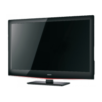
Details viewable size, TV system, and rear/side connector types.

Physical Specifications and Power

Provides physical dimensions, weight, and power consumption specifications.

Operating Instructions

Remote Control Functions

Explains the function of each button on the TV remote control for operation.

Menu Navigation and Settings

Guides on using OSD menus for picture, sound, TV, and feature adjustments.

Sound Menu Adjustments

Explains sound settings such as Sound Mode, Balance, Virtual Surround, and Digital Audio Out.

TV and Feature Menu Options

Covers TV menu settings, subtitle, teletext, and common interface configurations.

Software Updates and Care Tips

Guides on OAD operation for software updates and general care/warning tips.

Device Connections

Connecting External Interfaces

Explains connections for CI, AV, USB, Antenna, SCART, PC, Component, SPDIF, HDMI.

Front Panel Controls

Control Knobs Description

Details the function of each control knob on the TV's front panel.

Input/Output Specifications

Signal Connector Pinouts

Provides pinout details for VGA, HDMI, and Half SCART connectors.

Video and Audio Signal Parameters

Details RF, CVBS, Component, Audio, SCART, HDMI signal parameters.

Supported Video Input Formats

Lists video input formats supported by various interfaces.

Mechanical Instructions

Disassembly Procedures

Guides on unscrewing the stand, rear cover, and disconnecting wires for disassembly.

Board and Bezel Removal

Details removing main/power/IR boards, shield-IO, base support, and bezel.

Repair Flowcharts

Troubleshooting Common Issues

Flowcharts for no picture, abnormal display, no sound, no power, and no display.

Key Board Troubleshooting

Diagnoses issues with the key board, checking connections and button switches.

PCB Layouts

Main Board Layouts

Illustrates component and trace layouts for the main PCB.

Power Board Layouts

Details component and trace layouts for the power board.

Key and IR Board Layouts

Shows component layouts for the key and IR boards.

Adjustment Specifications

Color Temperature Details

Details color temperature specifications (CCT, x, y) for Warm, Normal, Cool.

Block Diagram

System Overview

Presents the overall system block diagram showing major ICs and connections.

Wiring and Schematic Diagrams

Wiring Diagrams

Illustrates wiring connections between major boards and components.

Schematic Diagrams

Provides detailed circuit schematics for main board, power, and other sections.

Exploded Views and Parts Lists

Exploded View Diagrams

Diagrams showing exploded views of A626N and A632N models with numbered parts.

Exploded Parts Lists

Lists mechanical, screw, and other parts by number and description for A626N/A632N.

Bill of Materials (BOM)

BOM - Key Components

Provides a detailed Bill of Materials listing parts by location, part number, and description.

Related product manuals