- 9 -
Checkout and Adjustment
Adjustments will vary since every antenna installation is not the same. Antenna performance is
influenced by nearby structures such as fences, building, other antennas, etc. A good antenna
analyzer is a must to determine resonance. You cannot rely on you radio SWR meter to give you an
accurate reading, especially when tuning the antenna for the first time.
NOTE: The two coil shorting straps (F) are provided as a means of decreasing the inductance of the
80 and 40 meter coils more than is possible simply by stretching the coils. Lower than normal
inductance may be necessary if the HF2V is top loaded as described later for the sake of greater
SWR bandwidth on 80/75 meters.
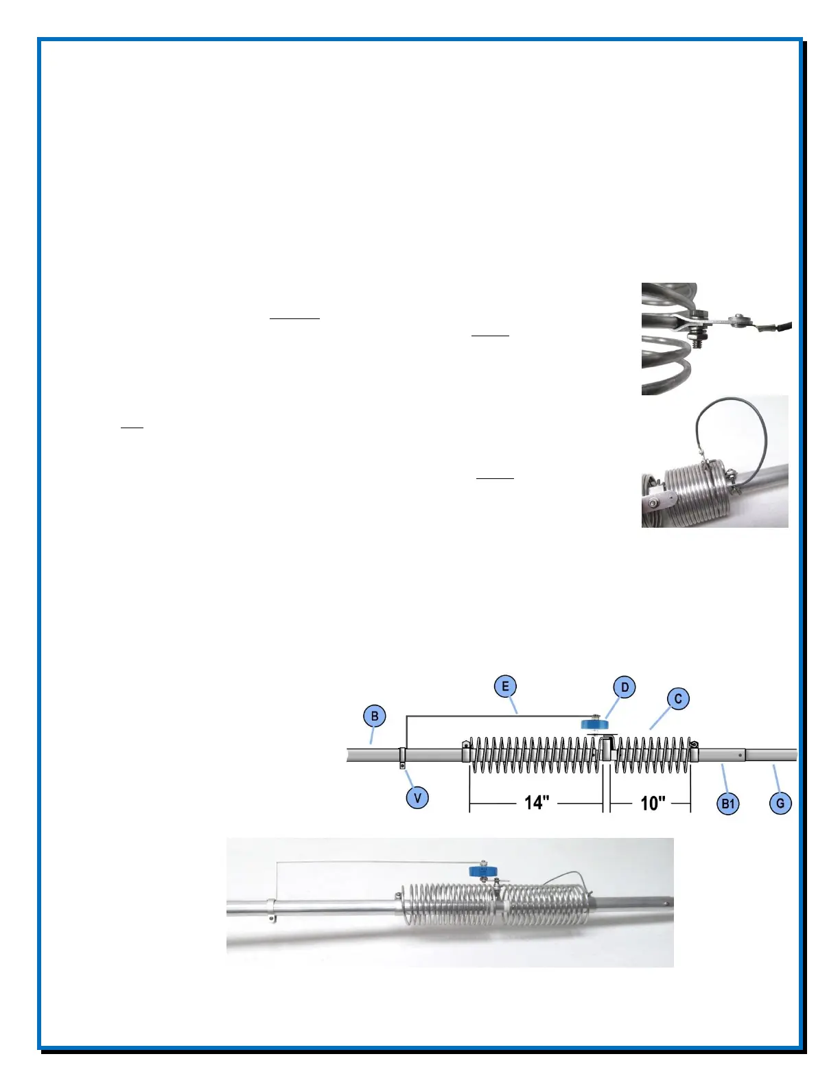
For operation of the HF2V without top loading or any optional accessories for
other bands attach the lug end of one shorting strap to the upper clamp of the 40
meter coil. This is done by removing the wing nut and other hardware from the
upper clamp and placing the lug end of the coil shorting strap (F) over the #10
bolt ahead of the locking washer and the wing nut. The other end (clamp end) of
the coil shorting strap (F) should be tapped down along the 40 meter coil so that
four full turns are shorted out. Secure it with #8 x 3/4 bolt, #8 lock washer, two
#8 flat washers and #8 hex nut.
The other shorting strap, if needed, may be attached to the lower clamp of the 80
meter coil and tapped upward along the coil for decreased inductance. Secure it
with #8 x 3/4 bolt, #8 lock washer, two #8 flat washers and #8 hex nut.
With no top loading, however, it is unlikely that any turns will need to be shorted to achieve
satisfactory operation over any 60 kHz segment of the 3500-4000 kHz range. For MARS or other
operation above 4000 kHz the shorting strap will probably be required.
With the 40 meter coil shorted as noted above and with the following coil settings resonance and
lowest SWR should occur at approximately 7150 and 3750 kHz. This is an approximate starting
point since antenna performance varies greatly depending on installation variations.
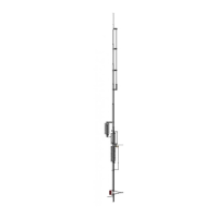
1. Set the 80 meter coil so that the
distance between the upper edge
of the lower coil clamp to the
lower edge of the center clamp
around the insulator is 14
inches. The 40 meter coil
should be adjusted so that the
distance between the lower edge
of the upper clamp and the upper
edge of the center clamp is 10 inches.
2. Accurate SWR measurements can be obtained at the antenna using a modern antenna analyzer.