2018/12 – B - Code : 33315
between the two tapping points (valve to control the flow rate through the heat pump).
To limit heat loss from the pipes, bury them underground (at a depth of 50 to 80 cm depending on the
region) or lag the pipes. In any case, minimize the amount of uninsulated pipe exposed to the air.
V.5) Wiring
The machine must be wired in by a qualified professional, after the hydraulic connections have been
completed. When dismantling the machine, disconnect it electrically before disconnected the hydraulic
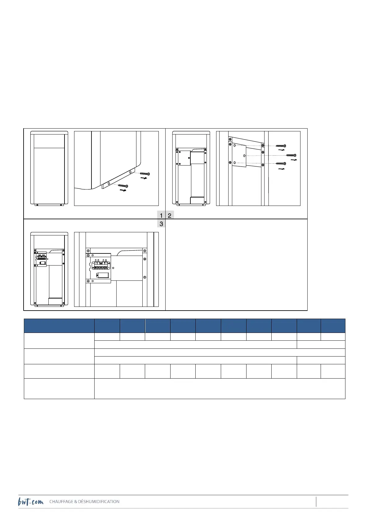
connections. The heat pump’s power cable connection terminal is located behind the socket. Use a cable with a wire
cross section that complies with the specification below, connected upstream to a breaking device rated
as set out in this table.
circuit breaker rating (A)
Power cable (wire cross
section in mm2)
Remote installed control
panel cable (wire cross
section inmm2)
*For a cable length less than 10 m. Increase the wire cross section if the cable is more than 10 m long. The cable
length should never exceed 50 m.
! IMPORTANT :
Damaged cables must be replaced immediately by a qualified professional.
When installing the device, make sure earth wiring will present an ohmic resistance level complying with local
regulation requirements.
Check the electrical connections at the various terminals annually, tighten if necessary.
The heat pump’s electrical and electronic components are not guaranteed against overvoltages produced by
lightning strikes. The electrical supply in the home must be adequately protected against this risk.
① Unscrew the 2 screws from the base of the panel on
the right hand side and remove the bottom section
of the panel.
② Remove the 3 screws from the lid of the electrical
box.
③ Connect the power cable according to the
standardised markings (NB: in 3ph installations, live wires
are marked R,S,T / in 1 ph installations, the live wire is
marked L).



 To Next Page