Do you have a question about the BYD Battery-Box LV Flex Lite and is the answer not in the manual?
Specifies the validity period and scope for the Battery-Box LV Flex Lite operating manual.
Defines the qualified persons and required skills for operating the battery system.
Provides a summary of the manual's structure and sections.
Confirms the battery system's compliance with applicable European directives.
Explains the hazard classifications (Danger, Warning, Caution, Notice) used in the manual.
Explains the meaning of various symbols used throughout the operating manual.
Lists abbreviations and their full designations used in the manual.
Defines the purpose, application, and operational modes of the battery system.
Covers essential safety guidelines for handling, leakage, fire, overvoltages, weight, and property damage prevention.
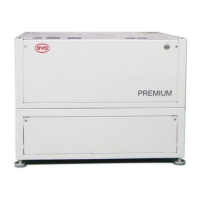
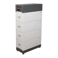
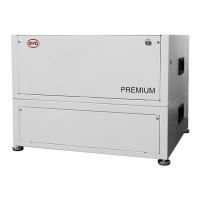
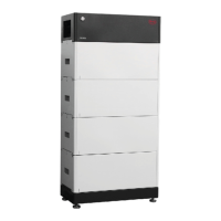
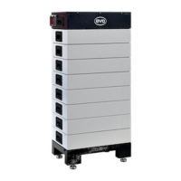
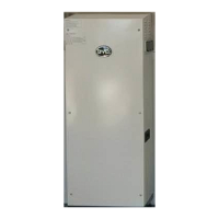
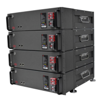
Explains the Battery-Box LV Flex Lite's function, compatibility with inverters, and components.
Details connection interfaces and software applications like Be Connect for system management.
Explains the meaning of various symbols found on the battery system itself.
Describes the meaning of different LED indicator states for system status and errors.
Specifies environmental and physical conditions for safe installation of the battery system.
Lists necessary tools required for the installation process.
Lists required safety gear and additional materials for installation.
Details the steps for installing modules without a rack and within a rack/cabinet.
Identifies and describes the various connection ports on the battery system.
Illustrates the overall electrical connection schematic for the battery system.
Provides instructions for proper grounding of the battery system.
Details connecting data cables between the inverter, BMU, battery modules, and router.
Instructions for connecting DC power cables to the battery system.
Step-by-step guide to safely power up the battery system.
Guide to setting up the battery system using the Be Connect app and firmware.
Instructions for activating and configuring the connected inverter with the battery system.
Procedure for safely switching on and initiating the battery system operation.
Steps to safely power down the battery system and its components.
Explains system responses to errors and interprets fault messages for diagnostics.
Details the meaning of LED signals on BMU and battery modules for error identification.
Provides detailed instructions for connecting data cables to various compatible inverter brands.
| Nominal Voltage | 51.2 V |
|---|---|
| Max Charge Current | 50 A |
| Max Discharge Current | 50 A |
| Operating Temperature | -10°C to +50°C |
| Depth of Discharge | 95% |
| IP Rating | IP55 |
| Warranty | 10 years |
| Battery Type | Lithium Iron Phosphate (LFP) |
| Operating Voltage Range | 44.8 V - 57.6 V |
| Peak Discharge Current | 100 A |
| Communication | CAN |
| Protection Class | Class I |
| Communication Interface | CAN, RS485 |