Do you have a question about the C-MORE EA1-TCL-M and is the answer not in the manual?
Provides an overview of the manual's purpose and scope for users.
Explains the typographical and iconographic conventions used throughout the manual.
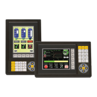
Details the features and specifications of the C-more 6” Color Micro-Graphic panel.
Lists the UL, cUL, and CE certifications obtained by the product.
Decodes the alphanumeric structure of panel and bezel part numbers.
Illustrates the information found on the product's identification label.
Explains the structure and meaning of serial numbers and date codes.
Provides a step-by-step guide for the initial setup and installation of the panel.
Lists the different C-more 6” Color Micro-Graphic panel models available for purchase.
Provides detailed technical specifications for the C-more 6” panel's display, features, and electrical properties.
Shows the physical dimensions and mounting cutout details for the panel.
Details the available communication ports, including USB and 15-pin serial, with pinout information.
Lists the compatibility of various chemicals with the panel's materials for safe usage.
Describes the software used to configure and program the C-more Micro-Graphic panel.
Details the 20-button bezel for landscape mounting, including features and specifications.
Details the 21-button bezel for portrait mounting, including features and specifications.
Describes adapters for connecting the panel's serial port at different angles or to terminal blocks.
Explains the optional clear screen overlay for protecting the panel's display.
Outlines essential safety precautions and responsibilities for installing and operating automation equipment.
Introduces the process of panel installation, including location selection and mounting.
Provides precise dimensions for cutting a panel opening for mounting the C-more 6” panel.
Covers essential guidelines for connecting power and communication wiring to the panel safely.
Introduces the panel's built-in System Setup Screens for configuration and testing.
Explains the procedure to enter the panel's System Setup Menu using function keys.
Visually represents the navigation structure of the System Setup Screens menu.
Describes how to navigate through the main selections within the System Setup Menu.
Details how to view panel information such as memory, protocol, extensions, and versions.
Covers adjustments for display brightness, beeper, calibration, memory, and other panel settings.
Explains how to perform communication tests, buzzer tests, and touch panel tests.
Introduces the panel's communication capabilities with AutomationDirect and third-party PLCs.
Lists the various PLC communication protocols supported by the C-more 6” panel.
Illustrates the panel's communication ports and their connections to PLCs.
Explains how to implement password protection for ladder programs in DirectLOGIC PLCs.
Provides charts for recommended cables and PLC compatibility for various PLC brands.
Guides users on how to interpret and utilize the PLC compatibility and connection charts.
Demonstrates a practical example of using the PLC compatibility charts.
Lists purchased cables for connecting the panel to various PLCs, including part numbers.
Provides wiring diagrams for creating custom communication cables for specific PLC connections.
Illustrates a wiring diagram for a multi-drop RS-422A network connection.
Illustrates a wiring diagram for a multi-drop RS-485A network connection.
Emphasizes the importance of backing up the application project during routine maintenance.
Guides users on verifying the panel's operating environment for temperature and humidity.
Details how to check the input voltage supplied to the panel to ensure it is within the operating range.
Advises checking TxD and RxD LED indicators for communication activity.
Recommends inspecting the panel for chemical damage, gasket integrity, and vent cleanliness.
Explains how to use built-in panel tests for communication, beeper, and touch screen functionality.
Advises reviewing panel settings like beep and orientation via the System Setup Screens.
Provides instructions for safely cleaning the panel's display screen.
Recommends verifying the operation of application screens and troubleshooting procedures.
Explains how to check panel status and update firmware using the programming software.
Provides steps to diagnose and resolve issues when the panel does not power on.
Offers solutions for troubleshooting a blank or unresponsive display screen on the panel.
Guides users on how to adjust display brightness and troubleshoot dim screens.
Explains how to resolve the "No User Program" message by downloading a project.
Provides steps to recover from lost firmware and enter Update Mode.
Details the process of updating the panel's firmware to match software versions.
Addresses troubleshooting steps for establishing communication between the panel and a PC.
Guides users on resolving communication issues between the panel and a connected PLC.
Introduces panel and PLC error codes and where to find detailed explanations.
Lists common runtime errors and general troubleshooting steps for the panel.
Explains how to reset the panel's settings to factory defaults to resolve issues.
Discusses potential issues caused by electrical noise and provides mitigation strategies.
Provides a summary and catalog of available replacement parts for the panel.
Lists specific part numbers for mounting clips, connectors, gaskets, and overlays.
Guides users on how to replace or customize the function key label insert.
Introduces the appendix and explains how panel and PLC errors are reported.
Lists panel-specific error codes, messages, and their potential causes.
Explains Modbus protocol error codes that may be displayed as P499 values.
Explains DirectLOGIC error codes, including K-Sequence and DirectNET protocols.
Lists error codes for DirectLOGIC K-Sequence protocol communications.
Lists error codes for DirectLOGIC DirectNET protocol communications.
Explains Allen-Bradley DF1 and DH485 protocol error codes as P499 values.
Lists error codes for Allen-Bradley DF1 protocol communications.
Lists error codes for Allen-Bradley DH485 protocol communications.
Explains GE SNPX protocol error codes as P499 values.
Lists error codes for GE SNPX protocol communications.
Lists error codes for Mitsubishi FX protocol communications.
Lists error codes for Mitsubishi Q/QnA/Q series PLC communications.
Explains Omron Host Link and FINS protocol error codes as P499 values.
Lists specific error codes for Omron Host Link protocol.
Lists specific error codes for Omron FINS protocol.
Explains Siemens PPI protocol error codes as P499 values.
Lists specific error codes for Siemens PPI protocol.
Introduces the appendix on runtime errors and their common causes.
Lists panel error codes, messages, and possible solutions for runtime issues.
| Resolution | 800 x 480 |
|---|---|
| Touch Technology | Projected Capacitive |
| Power Supply | 24 VDC |
| Display Type | TFT LCD |
| Touchscreen | Yes |
| Backlight | LED |
| Enclosure | Plastic |
| Operating Temperature | 0°C to 50°C (32°F to 122°F) |
| Communication Ports | Ethernet, USB |
| Connectivity | Ethernet |
| Ports | Ethernet, USB |