12 HW Installation
Power-on Sequence
To power on the board, follow the procedure below:
1. connect the 12V DC power supply to the DT5730/DT5725 through the DC input rear connector;
2. power up the DT5730/DT5725 through the ON/OFF rear switch.
See § Rear Panel to identify the relevant components
Power-on Status
At power-on, the module is in the following status:
• the Output Buffer is cleared;
• registers are set to their default configuration.
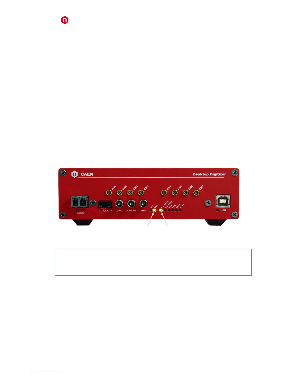
After the power-on, the front panel LEDs status is that only the NIM and PLL LOCK remain ON (see Fig. 12.1).
AFTER POWER-ON, CAEN RECOMMENDS TO PERFORM THE CHANNEL CALIBRATION AS DESCRIBED AT PAGE 22 IN
ORDER TO ACHIEVE THE BEST DEVICE PERFORMANCE