56 OMEGa with Bluefin
SCSI - 36F
J120
ADC3 #1-8
SCSI - 36F
J121
ADC3 #9-16
SCSI - 36F
J101
ADC2 #1-8
SCSI - 36F
J103
ADC2 #9-16
SCSI - 36F
J95
ADC1 #1-8
SCSI - 36F
J96
ADC1 #9-16
SCSI - 36F
SCSI - 36F
J122 J111
ADC2 #17-24
ADC3 #17-24
SCSI - 36F
J97
ADC1 #17-24
SCSI - 36F
J127
ADC3 #25-32
SCSI - 36F
J115
ADC2 #25-32
SCSI - 36F
J104
ADC1 #25-32
POWER 8DV
SCSI - 36F
J87
DAC3 #1-16
SCSI - 36F
J82
DAC2 #1-16
SCSI - 36F
J66
DAC1 #1-16
SCSI - 36F
J74
AES4-IN #1-16
SCSI - 36F
J88
DAC3 #17-32
SCSI - 36F
J83
DAC2 #17-32
SCSI - 36F
J68
DAC1 #17-32
SCSI - 36F
J75
AES4-OUT #1-16
SCSI - 36F
J57
AES3-IN #1-16
SCSI - 36F
J58
AES3-OUT #1-16
SCSI - 36F
J47
AES2-IN #1-16
SCSI - 36F
J48
AES2-OUT #1-16
SCSI - 36F
J62
AES1-IN #1-16
SCSI - 36F
J63
AES1-OUT #1-16
SCSI - 36F
SCSI - 36F
J67 J49
AES2-IN #17-32
AES3-IN #17-32
SCSI - 36F
J41
AES1-IN #17-32
SCSI - 36F
J69
AES3-OUT #17-32
SCSI - 36F
J51
AES2-OUT #17-32
SCSI - 36F
J42
AES1-OUT #17-32
SCSI - 36F
J76
AES4-IN #17-32
SCSI - 36F
J77
AES4-OUT #17-32
9M D-TYPE
DEBUG 2
J113
9M D-TYPE
DEBUG 1
J108
RJ45-8V
FAST LINK
J112
9F D-TYPE
POWER 5DV
J100
CH
J99
L2
BNX
005-01
L1
BNX
005-01
J102
TTL SYNC I/P
H121
H122
METER DATAVIDEO SYNC I/P
J109
RJ45-8V
BNC
75
BNC
75
DC DIST
FAIL BOX
HN5638 PROCESSING RACK BACKPLANE
J32
J106
0L
J55
CH
J107
CR
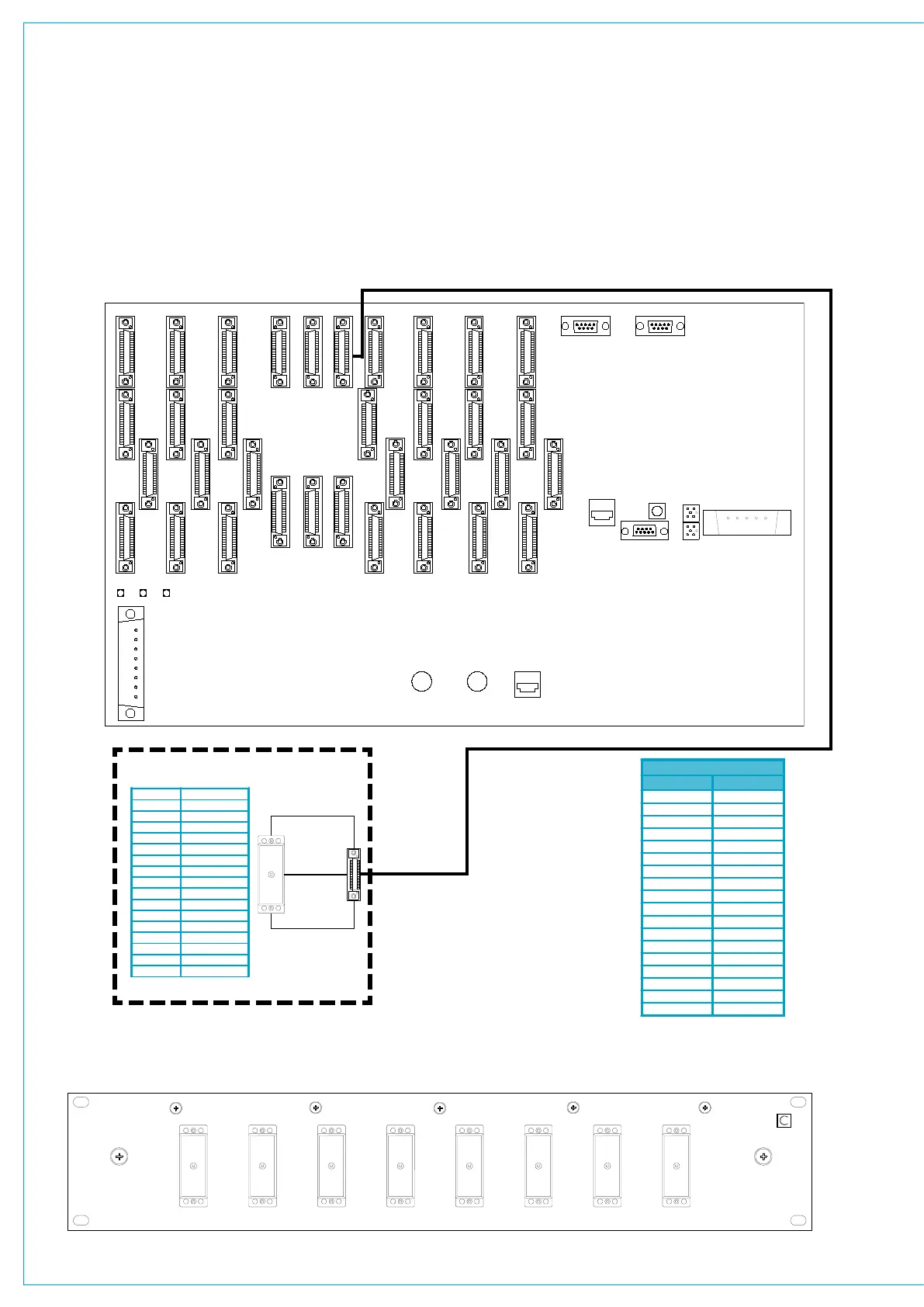
Each analogue output (DAC) card
in the Processing Rack, provides 16
stereo outputs. The cards are in-
serted into the slots within the rack,
these are numbered 1-3. Each slot
has 2 dedicated output connectors
on the rear of the rack, which provide
connections for the system’s analogue
outputs.
Via SN5075 SCSI to 38W EDAC converter card
- Rear of Interface Panel
Style 1 - 8 pairs per 38 way EDAC
Stereo Outputs 1-8
SCSI - 36F
STEREO LINE OPs 1-8
SN5075
On EDACs, the first pin is HOT (phase), the second pin is COLD (anti-
phase) and H.LL are chassis connections.
8 WAY EDAC INTERFACE PANEL
analOGuE lInE Outputs - stylE 1
Each of the output connectors provides
connections for 8 stereo outputs. The
diagram below shows how 8 way EDAC
interface panels are connected to the
DAC connectors on the rear of the rack
via SCSI style cabling to achieve Style 1 (8
pairs per EDAC connector).
2 Cables are required for each DAC card
fitted - 8 stereo outputs on each cable.
Ideally the EDAC interface panels should
be located within 5m (16.5ft) of the rack.
A.B Line OP 1L
C.D Line OP 1R
E.F Line OP 2L
J.K Line OP 2R
L.M Line OP 3L
N.P Line OP 3R
R.S Line OP 4L
T.U Line OP 4R
Z.AA Line OP 5L
BB.CC Line OP 5R
DD.EE Line OP 6L
FF.HH Line OP 6R
JJ.KK Line OP 7L
MM.NN Line OP 7R
PP.RR Line OP 8L
SS.TT Line OP 8R
H.LL Chassis
Cable 1 - Stereo Outputs 1-8
SCSI Pins
Circuit
1 . 19 Chassis
2 . 20
1L
3 . 21 1R
4 . 22 2L
5 . 23 2R
6 . 24 3L
7 . 25
3R
8 . 26 4L
9 . 27
4R
10 . 28 5L
11 . 29 5R
12 . 30
6L
13 . 31 6R
14 . 32
7L
15 . 33 7R
16 . 34 8L
17 . 35 8R
18 . 36 Chassis
 Loading...