SECTION 4: FLOW ®
making
since 1986
ater work
SECTION 4: FLOW
The Flow section of the controller is used for setting
up the following:
• Line Fill & Valve Close Times
• Alert Action settings
• Track Estimated / Learn Expecteds by
Program
• Pump Use by Program
• Master Valve/Flow Meter type, size, and K &
Offset values.
• Flow Checking parameters
• System Capacity parameters
• Valve On-at-a Time settings
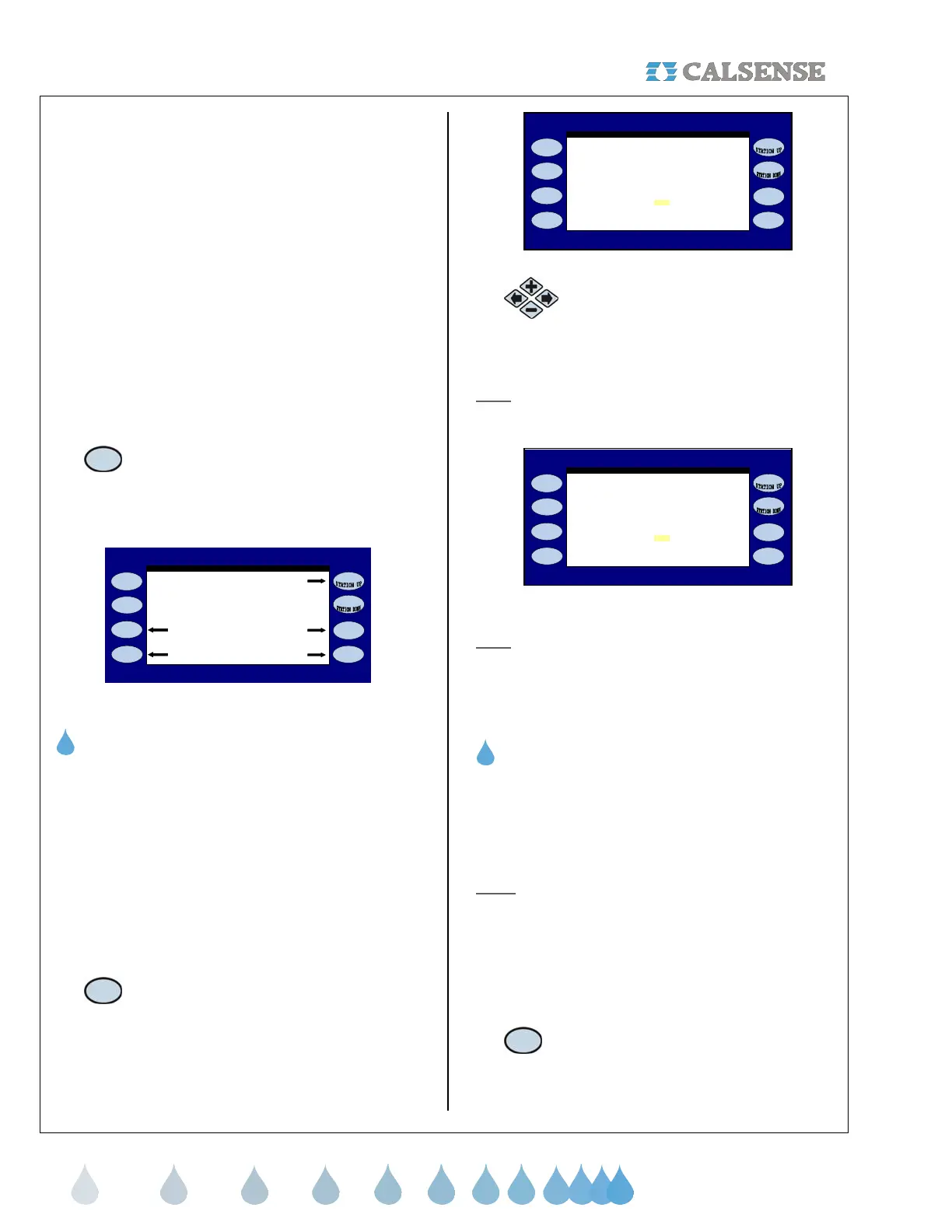
From the MAIN MENU screen:
1.
Press the FLOW Menu key.
The FLOW METER, MASTER VALVE & PUMP
screen is displayed (Figure 4.1).
FLOW METER, MASTER VALVE & PUMP
POC (MV & FM)
Pump On - at - a - Time
Track Estimated Mainline Capait
Figure 4.1
4A. TRACK ESTIMATED
The Track Estimated Water Use feature only
appears when NO FLOW METER IN USE and none
of the following are enbled:
• System Capacity
• Daily ET
• Budgets
If none of these items are in use, and you want to
track estimated water usage:
1.
Press the TRACK ESTIMATED Menu
key.
The TRACK ESTIMATED USAGE screen is
displayed (Figure 4.2).
flow rates for reports? NO
expected flow rates in your system.
TRACK ESTIMATED USAGE
presently there are no flow meters o
you must set the expected flow rate
for each station.
If you are interested in flow reports
Do you want to set the expected
Figure 4.2
2.
Press the PLUS or MINUS keys to
change the DO YOU WANT TO
SET THE EXPECTED FLOW
RATES FOR REPORTS? setting.
Note
: When the selection on the screen is changed
to YES, additional instructions will be displayed
(Figure 4.3).
flow rates for reports? YES
STATION PROGRAMMING screen)
Do you want to set the expected
you must set the expected flow rate
for each station.
If you are interested in flow reports
(set the expected flow rates on the
expected flow rates in your system.
TRACK ESTIMATED USAGE
presently there are no flow meters o
Figure 4.3
Note
: You will have to go back to the STATION
PROGRAMMING screen for each station and enter
an expected flow rate for each individual station.
THIS CONCLUDES THE TRACK ESTIMATED
SECTION
4B. POC (MV & FM) SETUP
The POC (MV & FM) setup is used to enter the type
and size of the Master Valve/Flow Meters connected
to this controller. You can also enter the K & Offset
values for FMBX style flow meters.
Note:
The multiple Master Valve / Flow Meter option
will only be available if the (-F) option is installed in
the controller. See Section 12 (-F) Option for more
information.
From the FLOW METER, MASTER VALVE & PUMP
screen (Figure 4.1).
1. Press the POC (MV & FM) Menu key.
The POINT OF CONNECTION (MV & FM) screen is
displayed (Figure 4.4).