SECTION 11: FLOWSENSE® (-FL) ®
making
since 1986
ater work
3. Press the PLUS or MINUS keys to
change the NO to a YES setting.
Note:
Each controller in the communications chain
must have the (-FL) option and will have to be set to
YES.
4.
Press the blue ARROW keys to
move the cursor to the next question.
NUMBER OF CONTROLLERS IN
SYSTEM ?.
5.
Press the PLUS or MINUS keys to
change the amount of controllers in
the system (Figure 11.2).
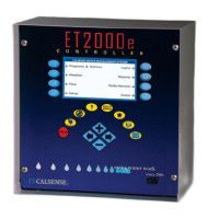
YES
Scan Results Controller Info
Communications Address: ! !
other controllers to share MASTER
VALVES, FLOW METERS, or PUMPS?
Number of controllers in System ? 2
ET2000e-40-M-SR-FL
602.a
does this controller coordinate with
Using FLOWSENSE Technolog
Figure 11.2
Repeat the process described above until all three
characters are set (The character furthest to the right
must be a letter).
Note: With multiple controllers one of the controllers
must be the Master with an address ending in a
Capitol “A”. All other controllers will have addresses
ending in B, C, D, etc. No two controllers can have
the same exact address when communicating to the
same central computer. The Master controller must
be the controller communicating back to the central.
If you desire to look at the controller’s
communications information:
6.
Press the CONTROLLER INFO
Menu key to go to the PART &
SERIAL NUMBERS screen
(Figure 11.3).
Note: This will allow you to look at the controller’s
ROM version, Baud Rates, Part number, and
Command center software version required to
communicate with this controller.
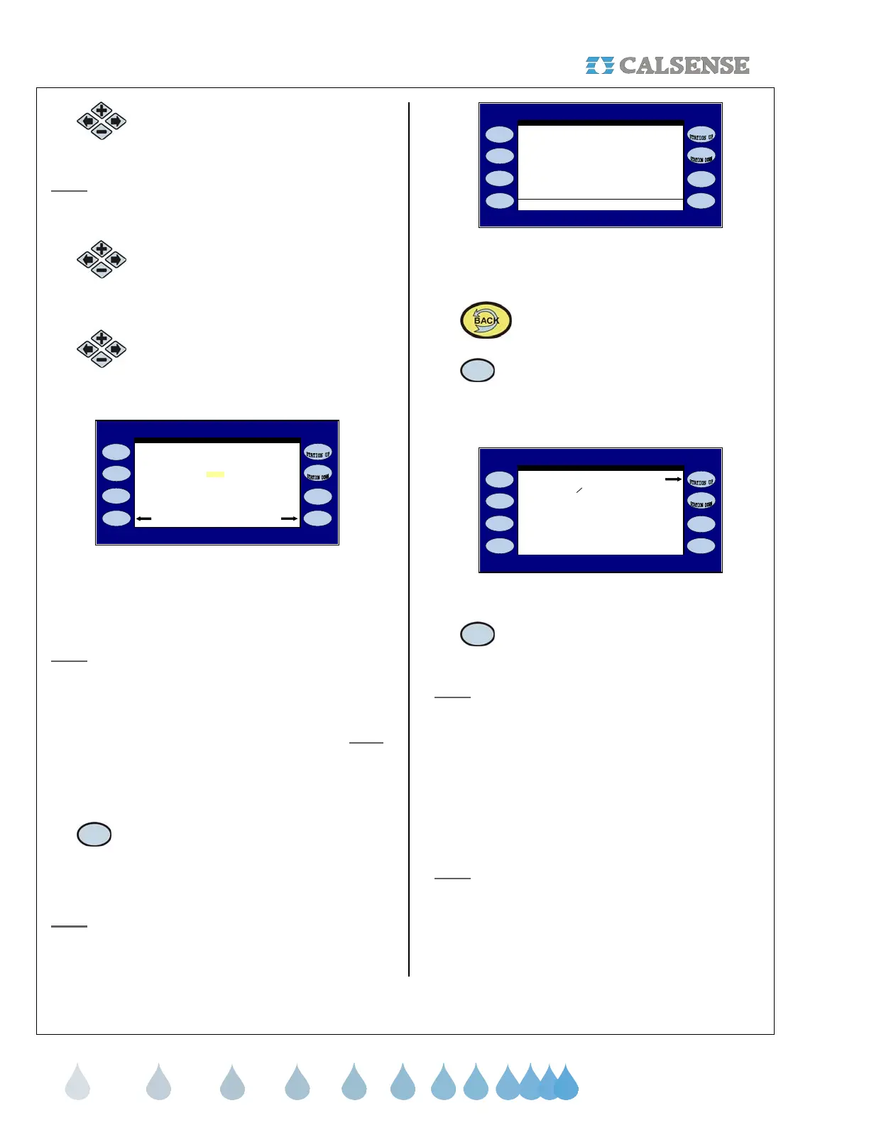
PART & SERIAL NUMBERS
ET2000e-48-M-SR-FL C=144000 D=9600
602.a s=1 c=6 A=14400 B=19200
Serial Num: 00000 CC4 Ver: 4.2.0.15
( the normally expected signal levels )
RTS CTS DTR DSR CD RI
Copyright Calsense Inc. 1987-2006
: L H L L L L
B: L L L L L L
C: L L L L L L
D: L L L L L L
Figure 11.3
You will have to perform a Controller Scan:
7.
Press the BACK key.
8.
Press the SCAN RESULTS Menu key.
The COMMUNICATIONS SCAN RESULTS screen
is displayed (Figure 11.4).
K - -
L - -
J - -
F - -
Found 1 of 2 in chain G - -
H - -
I - -
CHAIN DOWN A A ok
B - -
D - -
E - -
C - -
COMMUNICATION SCAN RESULTS
CHAIN DOWN !
start scan
Figure 11.4
9.
Press the START SCAN Menu key to
begin the scan.
Note:
The controller will scan each controller in the
chain.
• B “ - - “ symbol indicates that the
controller in the chain was unsuccessful
at communicating (The Master did not
find the “B” controller).
• B “ ok “ symbol indicates that the
controller was found and is currently
communicating with the master
controller (the “A” controller).
Note:
The scan can only be performed at the Master
controller in the FLOWSENSE® chain. Also the
“Number of controllers in chain.” can only be
adjusted at the master controller.
 Loading...