
R
Robert DonaldsonAug 2, 2025
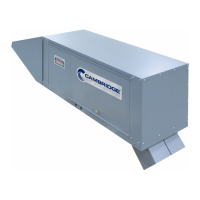
What to do if Cambridge Air Solutions Heater indicates a device fault?
- TTina MendezAug 3, 2025
If the Fault LED is on steady, it means a main code download is required. This could be because no application is loaded, the controller is in boot mode and needs a main code download, or there's a firmware mismatch between the PEAK controllers and the ZRF1811 Wireless Field Bus Router. In any of these cases, performing a main code download is the suggested solution.