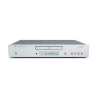
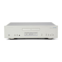
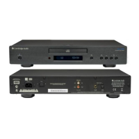
640C V2 SERVICE MANUAL – Revision 2
TABLE OF CONTENTS
Safety Precautions & Important Notes 3
Laser Safety Precautions
4
Exploded Diagram
5
Front Panel PCB Schematic (Issue 3)
6
Front Panel PCB Layout (Top Side)
7
Front Panel PCB Layout (Bottom Side)
8
Front Panel PCB Assembly BOM (Issue 2)
9
Front Panel PCB Assembly BOM (Issue 3)
10
Servo PCB Schematic
11
Servo PCB Layout (Top Side)
12
Servo PCB Layout (Bottom Side)
13
Servo PCB Assembly BOM
14-15
DAC Board PCB Schematic (Issue 6)
16
DAC Board PCB Schematic (Issue 7)
17
DAC Board (Supply) PCB Schematic (Issue 6)
18
DAC Board (Supply) PCB Schematic (Issue 7)
19
DAC Board PCB Layout (Top Side) (Issue 6)
20
DAC Board PCB Layout (Top Side) (Issue 7)
21
DAC Board PCB Layout (Bottom Side) (Issue 6)
22
DAC Board PCB Layout (Bottom Side) (Issue 7)
23
DAC PCB Assembly BOM (Issue 3)
24-25
DAC PCB Assembly BOM (Issue 6)
26-27
Mains PCB Schematic
28
Mains PCB Layout (Top Side)
29
Mains PCB Layout (Bottom Side)
30
Mains PCB Assembly BOM
31
Voltage Select Switch PCB Schematic
32
Voltage Select Switch PCB Layout (Top Side)
33
Voltage Select Switch PCB Layout (Bottom Side)
34
Voltage Selector PCB Assembly BOM
35
IC Pin Layout Details
36-44
2
 Loading...
