Do you have a question about the Cambridge Audio AR30 V2 and is the answer not in the manual?
Details power output, THD, frequency response, S/N ratio, and more.
Covers tuner bands, aerial inputs, signal-to-noise ratio, and distortion.
Lists THD and S/N ratio specifications for the iPod docking station.
Includes trigger outputs, power supply details, dimensions, and weight.
Controls power state and IR command reception.
Headphone jack connection and input source switching functionality.
Tuner tuning, display information, and band switching operations.
Display information and tuning mode control.
Front panel MP3 input and volume adjustment functions.
AC power socket, power switch, and loudspeaker connections.
AM/FM antenna, SIRIUS socket, and DD30 dock connector.
Trigger Out, Sub In/Out, Rec Out, and Audio Inputs.
F-type connector for DAB and FM antenna signals.
Covers reading instructions, general use, and specific warnings.
Addresses risks of fire, electric shock, moisture, and battery safety.
Explains lightning, WEEE, CE, C-Tick, and Ross Test symbols.
Details FCC rules and potential radio/TV interference.
Proper placement, heat management, and power source details.
Safety regarding electrical load, cleaning, and battery disposal.
Safe speaker connection and non-user-serviceable policy.
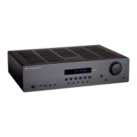
Visual breakdown of the main unit components.
List of parts for the main assembly.
Visual breakdown of front panel components.
List of parts for the front panel.
Parts for remote control and front panel components.
Lists ICs, transistors, and other components with part numbers.
Schematic for the Vacuum Fluorescent Display control.
Top-side copper trace layout for the display board.
Bottom-side copper trace layout for the display board.
Detailed schematic of the amplifier section.
Top-side copper trace layout for the amplifier board.
Bottom-side copper trace layout for the amplifier board.
Schematic detailing the power supply unit.
Top-side copper trace layout for the power supply board.
Bottom-side copper trace layout for the power supply board.
List of resistors and capacitors with part numbers.
Continuation of resistors and capacitors list.
List of capacitors, diodes, and transistors.
List of various capacitors and inductors.
List of connectors, sockets, and other parts.
List of relays, resistors, and filters.
Further list of capacitors and resistors.
List of diodes, transistors, and integrated circuits.
List of resistors and various connectors.
List of capacitors, diodes, transistors, and ICs.
List of capacitors, diodes, and transistors.
List of transistors, connectors, and power-related parts.
List of chassis parts, knobs, and fasteners.
List of accessories like bags, labels, and various screws.
List of screws, washers, desiccant, and heat shrink tubes.
Pin configurations for common transistors.
Pin configurations for STC810M and PT2257-S ICs.
Pin configurations for PT2319, FM3130, JRC4560, and R5F21258SNFP ICs.
Pin configurations for LD1117, 4053, 74HCT14, and TC7WH08FU ICs.
Pin configuration for 2SA1693 transistors.
Pin configurations for 2SC4466 and 2N5551 transistors.
Pin configurations for S8050 and C8550 transistors.
Pin configuration for C9014 transistors.
Pin configurations for LM2595T, KA7812, and KA7912 ICs.
Pin configuration for the 8050 component on the VFD PCB.
Pin configurations for 8550, 9014, and 9015 transistors.
Pin configuration for the PT6311 IC.
| Brand | Cambridge Audio |
|---|---|
| Model | AR30 V2 |
| Category | Stereo Receiver |
| Language | English |


 Loading...