CXC
7
1 2 3 4 5
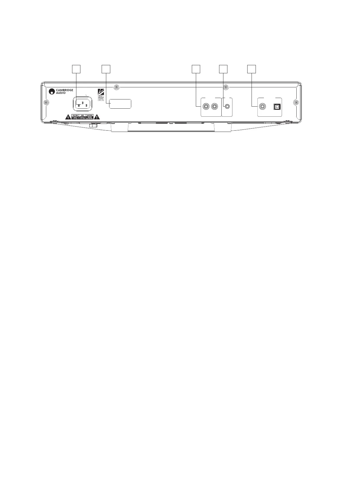
Rear panel controls
1. AC POWER SOCKET
Once all other connections are made, connect the supplied power cable
to the CXC power socket and to an appropriate mains socket. The CXC is
now ready for use.
2. MAINS VOLTAGE SELECTOR SWITCH
Switches the CXC mains voltage between 115V and 230V.
Note: For use by Cambridge Audio service personnel only!
3. CONTROL BUS
In – An RCA phono socket that enables un-modulated commands from
multi-rooms systems or other components to be received by the CXC.
Out – An RCA phono socket that provides control bus output commands
for further downstream units.
In Out
InOut
S/P DIF
Co-axial
Toslink
Optical
Digital Outputs
Digital Outputs
IR In Control Bus
IR InControl Bus
Mains Voltage Selector Switch:
100-120V/220-240V AC~50/60Hz
Power AC
Max Power Consumption: 25W
Designed & Engineered in Great Britain
Assembled in China
CXC
Compact Disc
Transport
4. IR (INFRA RED) IN
A 3.5mm mini-jack socket that enables modulated IR commands from
multi-room or IR repeater systems to be received by the CXC.
Note: Commands received by the IR In socket are not looped out of
the Control Bus. Refer to the 'Custom Installation' section for more
information.
5. DIGITAL INPUTS
The CXC has two digital outputs in total, S/P DIF co-axial and Toslink
optical sockets.
Coaxial – To obtain best results, use a high quality 75 ohm digital RCA
interconnect cable (not one designed for normal audio use).
Toslink Optical – Use a high quality TOSLINK bre optic interconnect
cable designed specically for audio use.