EasyManua.ls Logo

Cambridge Audio 640C Service Manual

Cambridge Audio 640C
34 pages
To Next Page IconTo Next Page
Page #1 background imageLoading...
Page #1 background image
Gallery Court Hankey Place London SE1 4BB UK
Tel: +44 (0)20 7940 2200 Fax: +44 (0)20 7940 2233
640C
Issue Date: 22
nd
December 2004
________________________________________________________________________
SERVICE MANUAL
________________________________________________________________________
SPECIFICATIONS:
D/A Converter Wolfson
WM8740
24-Bit/192kHz
Capable
Freq response (-0.5dB) 10Hz to 20kHz
THD <-92dB
Dynamic Range <105dB
Channel Separation >75dB
Jitter (correlated) <260pS
Digital Outputs Opt and Coax
Dimension (mm) (H x W x D) 70 x 430 x 310
Weight (kg) 4.6
AP14839/2
1
Question and Answer IconNeed help?

Do you have a question about the Cambridge Audio 640C and is the answer not in the manual?

Cambridge Audio 640C Specifications

General IconGeneral
BrandCambridge Audio
Model640C
CategoryCD Player
LanguageEnglish

Summary

Service Manual

Specifications

Key technical performance parameters of the Cambridge Audio 640C CD Player.

Safety Precautions & Important Notes

Chip Component Replacement Notes

Guidelines for replacing chip components and handling tantalum capacitors safely.

Laser Safety Precautions

Handling the Optical Pick-up Block

Precautions for handling the optical pick-up block to prevent electrostatic damage.

Laser Diode Emission Check

Safety guidelines for checking laser diode emission from a safe distance.

Exploded Assembly Drawing

Main Assembly BOM (Silver Unit)

Front Panel PCB Schematic

Front Panel PCB Layout (Top Side)

Front Panel PCB Layout (Bottom Side)

Front Panel BOM (Silver Unit)

Servo PCB Schematic

Servo PCB Schematic (Power Supply)

Servo PCB Layout (Top Side)

Servo PCB Layout (Bottom Side)

Servo BOM

DAC PCB Schematic

DAC PCB Layout (Top Side)

DAC PCB Layout (Bottom Side)

DAC BOM

Mains Input Schematic

Mains Input PCB Layout (Top Side)

Mains Input PCB Layout (Bottom Side)

Mains Input BOM

IC Pin Layout Details

Front Panel PCB IC Pin Layout

Pin configuration for the PIC16C505 (U3) IC on the front panel PCB.
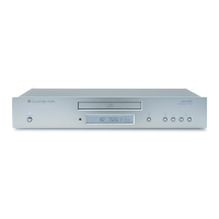
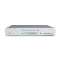
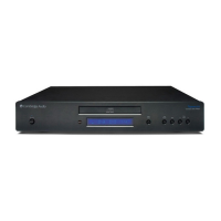
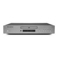
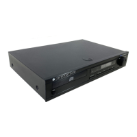
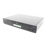
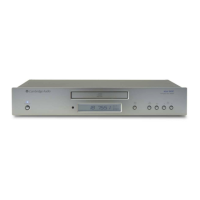
DAC PCB IC Pin Layout

Servo PCB IC Pin Layout

TA2153FN (U1) IC Pinout

TLCS-870 MCU (U3) Pinout

TA2092 (U6) Pinout

Silver - Black Differences BOM

Related product manuals