Cambridge Engineering, Inc. 28 S-Series Technical Manual
mWARNING:
Any gas leak detected must be repaired before unit
is placed into service.
e. Turn the blower and burner service switches to the
“OFF” position.
f. Reconnect the wire to terminal #3 on the amplifier
g. When performing a start-up proceed to the next
step, otherwise perform Final Heater Preparation
(page 29).
10. GAS VALVE LEAK CHECK
All heaters should be evaluated for the gas tightness
of the gas valve seat. Heaters rated over 400,000
Btu/hr are equipped with a leak test facility to assist
in checking this seal. A momentary switch and a
gas port for measuring pressure between the valves
are provided for leak testing. Refer to the Individual
Component Description Section for more information
regarding the leak test switch (page 70).
a. Connect a 0-10" WC manometer to the 1/8" NPT
fitting on the manual shut-off valve located just
prior to the burner and verify the manometer is
properly zeroed.
b. On single redundant valve applications (heaters
rated less than or equal to 400,000 Btu/hr), close
the manual burner shut-off valve and wait 30 sec-
onds to read the manometer. If the reading is great-
er than 0" WC, replace the gas valve and retest. If
the reading is 0" WC, remove the manometer and
reinstall the pipe plug.
On separate redundant valve applications, close
the manual burner shut-off valve, hold the momentary
leak test switch in the closed position and wait 30 sec-
onds to read the manometer. If the reading is great-
er than 0" WC, refer to the Maintenance Instruction
Section for information on Gas Valve Cleaning for
the safety shut-off gas valve closest (SSV) to the
burner and retest. If the reading is 0" WC, remove
the manometer and reinstall the pipe plug.
To check the gas tightness of the SOV shut-off
valve in the gas train, connect the manometer to the
leak test port between the valves and wait 30 sec-
onds to read the manometer. If the reading is greater
than 0" WC, refer to the Maintenance Instruction
Section for information on Gas Valve Cleaning
for the shut-off gas valve farthest from the burner
(SOV) and retest. If the reading is 0" WC, remove
the manometer and reinstall the pipe plug.
11. FINAL HEATER PREPARATION
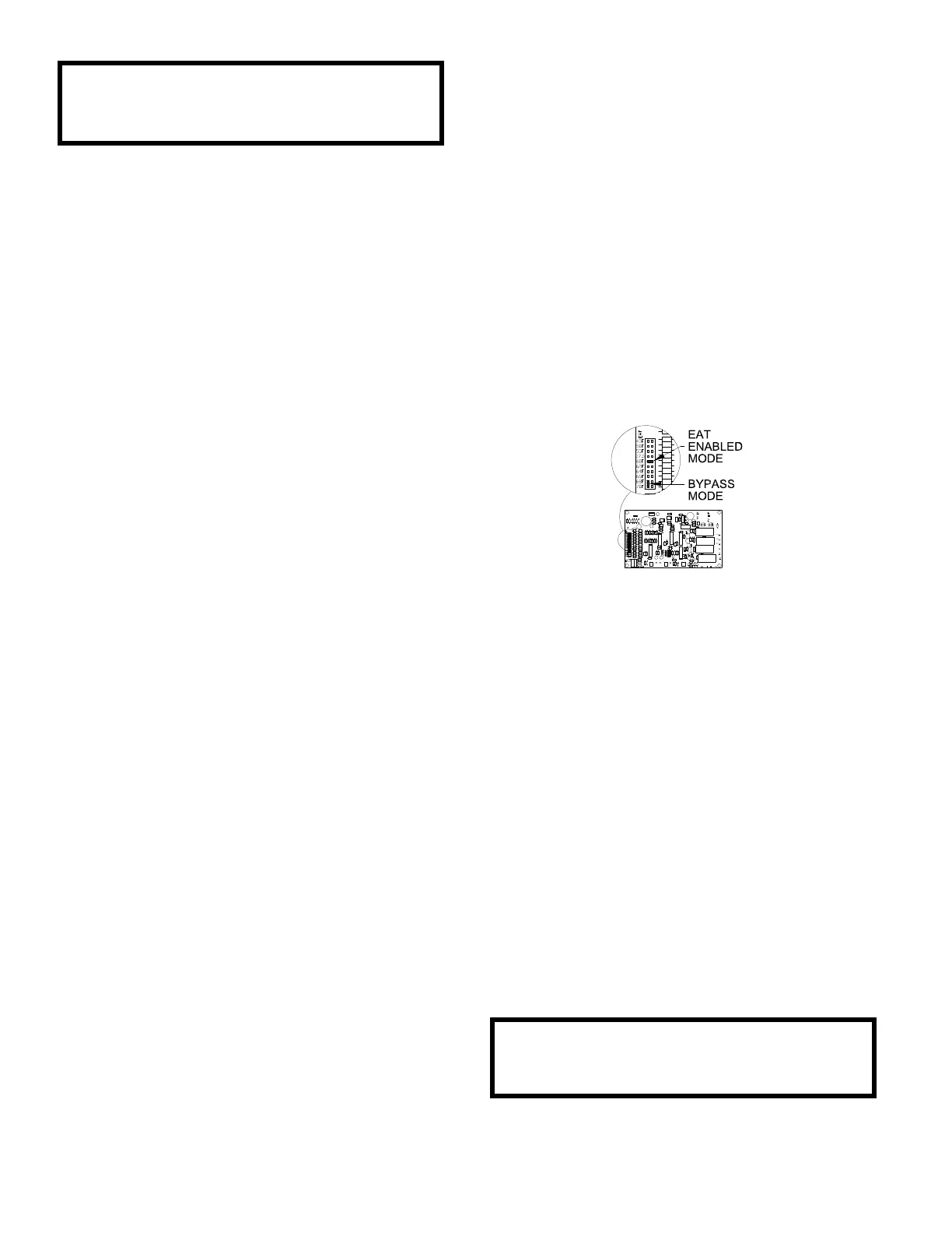
a. On EDSM and EDSM/TP control systems, if the
ambient temperature is at or above the Entering
Air Thermostat (EAT) set point and the Remote
Control Station Check has not been performed,
then the EAT must be adjusted in the heater. Note
the set point position and pull the jumper off the
temperature set point (EAT Enabled Mode) and
reinstall it sideways on the terminal block (Bypass
Mode) as shown in Figure 1. Refer to the Individual
Component Description section for additional infor-
mation.
Figure 1
b. Ensure the discharge temperature setting(s)
comply(ies) with the application specifications.
c. If inlet ducting is utilized, determine the time
required to purge it with four (4) air changes and
select a pre-purge time that will accommodate this
time. Refer to Individual Component Description
for additional information on the multi-functional
PC board.
d. Perform a visual inspection of all wiring and gas
valve plugs to ensure they have been properly
replaced.
e. Return the Technical Manual and the Wiring
Diagram to the manual holder.
f. Turn the blower and burner service switches to the
“REMOTE” position.
mWARNING:
All safety controls must be returned to normal
operating conditions.