Cambridge Engineering, Inc. 72 S-Series Technical Manual
door temperature reaches the EAT setpoint (45, 50, 55,
57.5, 60, 62, 64, 66, 68 or 70˚F).
4) The PT (Purge Timer) circuit function is preset at
the factory to provide four air changes within the heater
cabinet prior to an ignition attempt (normally set at 4 or
8 seconds). If inlet ducting is attached to the heater, the
delay time can be increased to 8, 16, or 32 seconds, as
applicable.
5) The patented LFS (Low Fire Start) circuit function
is provided to limit the initial heater firing for the first 15
seconds of a heating cycle. The voltage to the modulat-
ing valve is adjusted between 9 and 13 Volts DC by an
adjustable potentiometer on the PC board.
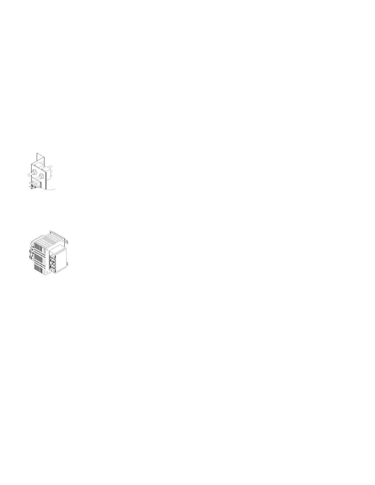
SERVICE SWITCH (SW1, SW2, SW3)
The service switches are mounted in the
electrical control enclosure. In the
“LOCAL” or “OFF” position, the service
technician has local control of the heater.
These switches must be placed in the
“REMOTE” position for normal control
from the remote control station.
TRANSFORMER (T1, T2)
Heaters supplied with an output of
greater than 400,000 Btu/hr are fur-
nished with a dual voltage transform-
er unless the supply voltage is 115
volts. The transformer furnished
depends on the supply voltage (208,
230, 460 or 575 volts). This transformer provides the
secondary control voltage of 24 and 115 Volts. Heaters
rated below 400,000 Btu/hr or supplied for 115 Volts are
furnished with the 24 Volt secondary transformer only.
Secondary fusing is provided in all Class I transformer
circuits to protect the downstream components from
short circuit. Fuse sizing is as follows: FNM-6.25 for
150 VA 24 Volt; FNM-1.6 for 150 VA 115 Volt; and
FNM-2.25 for 200 VA 115 Volt. Consult the heater wir-
ing diagram to identify the proper fusing. Do not
increase the fuse rating over that which is specified.