Switch PoE
VAS/101 VAS/101
M2M1
Switch
Switch
B
Switch PoE
Switch PoE
VAS/101 VAS/101
M2M1
Switch
Switch
VAS/101
M2M1
Switch
Switch PoE
Switch PoE
VAS/101
VAS/101
Switch
VAS/101
M2M1
+–
®
192.168.1.5 192.168.1.100
192.168.1.5 192.168.1.100
®
Switch PoE
®
192.168.1.5 192.168.1.100
192.168.1.5 192.168.1.100
C D
Page 5 - Manual code: FB00162-EN vers. 1 07/2015 © CAME s.p.a. - The data and information shown in this manual are to be considered as subject to change at any time and without the need for any advance warning.
Page 4 - Manual code: FB00162-EN vers. 1 07/2015 © CAME s.p.a. - The data and information shown in this manual are to be considered as subject to change at any time and without the need for any advance warning.
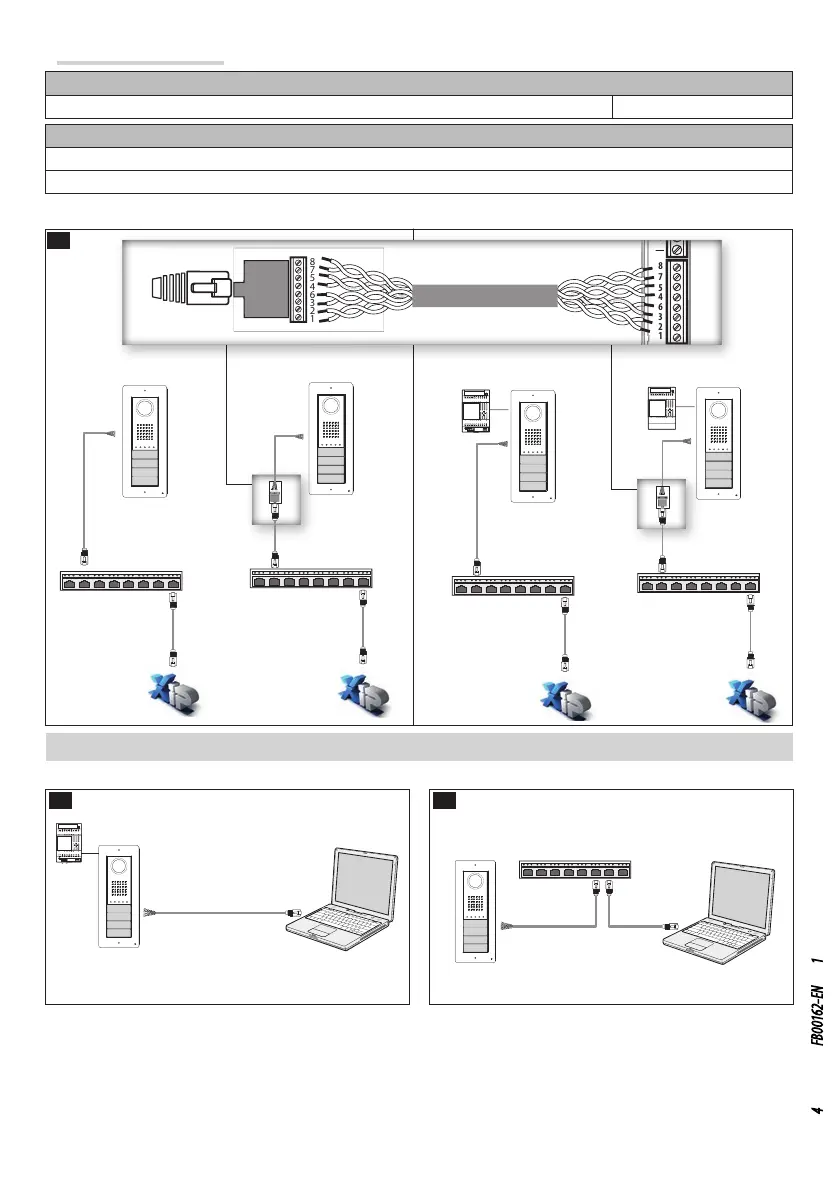
Installation diagrams B
Diagram for installation with devices powered by PoE Switch
Maximum distance between POE switch and Entry Panel with UTP CAT5, UTP CAT6 cable: 100m.
Diagram for installation with locally powered devices
With VAS/101 power supply: 1 DVC/IP, 100m cable with 1 mm
2
section
With VAS/100.30 power supply: up to 2 DVC/IP devices, 100m cable with 1 mm
2
section
Settings and commissioning via WEB interface and PCS/XIP
To configure the device via WEB interface, assign your PC an address belonging to the same subnet as the device. The default IP
address is 192.168.1.5 with netmask 255.255.255.0.
If the device is powered locally, it is possible to connect it directly to your PC, via a LAN cable C.
If the device is powered by PoE switch, the connection diagram is as shown in figure D .
 Loading...