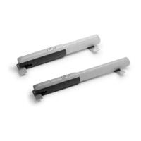
The CAME ATS-S3 is a complete kit designed for automating swing gates, capable of handling gates weighing up to 400kg and with a maximum width of 3m. This system is intended for installation by skilled and qualified personnel, ensuring a high degree of safety and problem-free operation when correctly installed and maintained according to regulations.
Function Description:
The ATS-S3 kit provides automated opening and closing functionality for swing gates. It includes a motor, control panel, remote controls, and safety devices like photocells. The system allows for both automated operation and manual release in case of power failure or malfunction. The control panel, ZA3P, manages the gate's movements, safety inputs, and programming of transmitters.
Important Technical Specifications:
- Gate Capacity: Up to 400kg weight, 3m width.
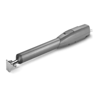
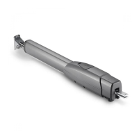
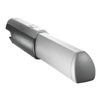
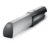
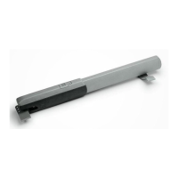
- Motor: ATS30AGS gate motor.
- Control Panel: ZA3P.
- Power Supply: Mains supply 230 V AC.
- Photocells: DIR photocells, available in 10m, 20m, and 30m ranges. They operate on 12-24 V AC-DC.
- Transmitters: TOPD4FXM (fixed code, dual-frequency, 4-button) with a maximum capacity of 25 individual buttons.
- Antenna: TOP-A433N tuned antenna, using RG58 cable with a maximum length of 5m.
- Cable Lengths:
- Mains Supply (230 V AC): 3 Core 1.5mm for 1-20m, 3 Core 2.5mm for 20-30m.
- ATS30AGS Gate Motor: 3 Core 1.5mm for 1-20m, 3 Core 2.5mm for 20-30m.
- DIR Photocells: RX 4 Core 0.5mm Flex, TX 4 Core 0.5mm Flex, 1-30m.
- IP Rating: Control panel enclosure maintains an IP54 protection rating when all holes are sealed.
- Safety Inputs: The control panel supports various safety inputs (C1, CX) which can be configured for different reactions (reopening during closing, reclosing during opening, partial stop).
Usage Features:
- Typical Gate Setup: The system includes components like the ATS motor, control panel, reception antenna, flashing light (optional), selector keypad (optional), photocells (on outside of gate posts), a second set of photocells (optional), mechanical end stop (not supplied), and photocell column (optional accessory).
- Side Hung Gate Geometry: Specific measurements (A, B, E, F, C max.) are provided for different opening angles (90°, 120°) to ensure correct installation and optimal performance. The bracket holes allow for adjustment of the opening angle.
- Manual Release: The ATS telescopic swing gate operators feature a manual release lock beneath a hatch on the top of the motors. This allows for manual operation of the gate in case of power failure. To release, open the hatch, insert the key, turn clockwise, and manually open the gate. To re-engage, close the gate, turn the key back to its original position, and ensure it is fully engaged.
- Transmitter Programming:
- Adding a Transmitter Button: Press and hold the CH1 button until the PROG. LED flashes rapidly. While holding CH1, press and release a button on the transmitter. The PROG. LED will become solid, indicating successful saving. Release CH1. A maximum of 25 individual buttons can be saved.
- Removing All Transmitters: Press and hold both CH1 and CH2 buttons simultaneously until the PROG. LED stays lit. All previously saved transmitter buttons will be removed.
- Safety Inputs Configuration: The ZA3P control panel allows for programming how the gate reacts when a safety circuit (e.g., photocell beam) is triggered.
- C1 Reopening During Closing: If triggered during closing, the automation stops and reverses motion until fully open. If auto closing is enabled, the countdown resumes. If auto closing is not enabled, it waits for another command.
- CX Reclosing During Opening: If triggered during opening, the automation stops and reverses motion until fully closed. It requires another activation to restart.
- CX Partial Stop: If triggered during operation, the automation stops. If auto closing is enabled, the countdown resumes. If auto closing is not enabled, it waits for another command.
- Quick Start Guide (ZA3P): Provides a step-by-step process for initial setup, including:
- Powering on the control panel.
- Disabling total stop (link wire between terminal 1 & 2).
- Disabling safety input C1 if no device is connected (link wire between terminal 2 & C1).
- Disabling safety input CX (Dip switch 8 on).
- Setting all other dip switches off.
- Checking motor direction and setting ATS microswitch end stops.
- Adjusting potentiometers (TL, TRM2) for optimal operation.
- Checking gate operation by pulsing across connections 2 & 4.
- Note: Safety inputs must be configured and gate force tested after initial setup.
Maintenance Features:
- Regular Servicing: Ensure the gate is serviced at 3 to 12 month intervals (dependent on number of openings) by an installation/maintenance company.
- Malfunction Reporting: Report any signs of malfunction to the installation/maintenance company immediately.
- Malfunction Procedure: In case of malfunction, isolate the power supply, release any additional locking mechanism, manually open the gate (refer to the manual release instruction booklet), and call the installation/maintenance company.
- Manual Release Maintenance: Open the manual release cover and spray the locking mechanism with suitable penetrating lubricant.
- Hinge Lubrication: Lubricate gate hinges.
- Monthly Manual Release: Manually release the gates at least once per month.
- Photocell Beam Reaction: When the photocell beam is broken, the control panel can be programmed on how to react. Refer to the 'Safety' section for more information.
- Control Panel Access: Only a competent service provider should open the enclosure and adjust the settings.
- Photocell Installation: Photocells should be installed between 500-600mm from the ground, facing each other. Power is taken from the control panel 24v AC. The maximum range of the photocell should always be observed.
Safety Instructions:
- Do not allow children to play near the gate.
- Keep all remote control operating devices out of the reach of children.
- Do not pass through the gate whilst in operation; wait until it is fully open.
- Do not stop unnecessarily when passing through the gate.
- Keep feet away from the bottom of the gate during operation.
- Do not operate the gate by remote control unless they are in view.
- Do not attempt to block or interfere with the gate movement.
- Under no circumstances should you attempt to modify the gate automation system.
- If in doubt about gate operation, call the installation/maintenance company.
- Always isolate the power supply when performing maintenance or in a power cut.
- Release any additional locking devices fitted to the gate (e.g., electric lock) before manual release.
- The above sequence (safety input triggered 3 times) will be attempted 3 times before the automation is halted, requiring activation from a command device to restart.
- If during the reverse motion a different safety is triggered, the automation will perform the appropriate action for the new triggered safety, should multiple safeties be triggered at the same time the automation will be halted at its current position.