Documentazione
Tecnica
49
rev. 4.5
08/2002
©
CAME
CANCELLI
AUTOMATICI
CANCELLI AUTOMATICI
SCHEDA COMANDO
CONTROL BOARD
CARTE DE COMMANDE
STEUERPLATINE
TARJETA DE MANDO
ATI
ITALIANO/ ENGLISH/ ESPAÑOL
119D49-1
SERIE ATI |
ATI SERIES
|
SERIE ATI
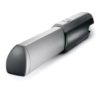
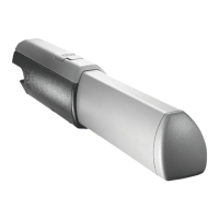
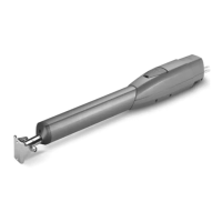
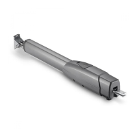
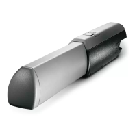
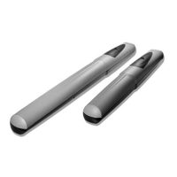
1) Motoriduttore
2) Quadro comando
3) Ricevitore radio
4) Fotocellule di sicurezza
5) Selettore a chiave
6) Antenna
7) Lampeggiatore di movimento
8) Trasmettitore radio
1) Irreversible gear motor
2) Control panel
3) Radio receiver
4) Safety photocells
5) Key-operated selector switch
6) Antenna
7) Flashing light indicating gate movement
8) Radio transmitter
1) Motorreductor irreversible
2) Cuadro de mando
3) Radiorreceptor
4) Fotocélulas de seguridad
5) Selector a llave
6) Antena
7) Lámpara intermitente de movimiento
8) Transmisor
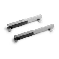
Automazione esterna per cancelli a battente
External automatic opening system for wing gates
Automatizacion exterior para puertas batientes
Wiring for microswitches:
5 x 1mm
2
Power wires to motor:
2 x 1,5 mm
2
up to 20 m;
2 x 2,5 mm
2
up to 30 m
Cavi di collegamento microinterruttori:
5 x 1 mm
2
Cavi di alimentazione motore:
2 x 1,5 mm
2
fino a 20 m;
2 x 2,5 mm
2
fino a 30 m.
Cables de conexión microinterruptores:
5 x 1 mm
2
Câbles de alimentación motor:
2 x 1,5 mm
2
hasta 20 m;
2 x 2,5 mm
2
hasta 30 m
A 3024 - A 5024
Impianto tipo
Standard installation
Instalacion tipo
4 x 1,5
2 x 1 - TX
4 x 1
2 x 1,5
3 x 1,5
2 x 1
3 x 1
230 V
4 x 1 - RX
T RG58
4 x 1,5
8
1
1
5
4
3
4
2
4
4
7
6