Documentazione
Tecnica
U12
rev. 1.0
07/2006
©
CAME
CANCELLI
AUTOMATICI
SCHEDA COMANDO
CONTROL BOARD
CARTE DE COMMANDE
STEUERPLATINE
TARJETA DE MANDO
Kit A3000A
ITALIANO/ ENGLISH/ ESPAÑOL
119DU12-1
SISTEMI COMPLETI ATI <|>
ATI SET COMPLETE
<|>
EQUIPOS COMPLETOS ATI
4 x 1,5
2 x 1 - TX
4 x 1
2 x 1,5
3 x 1,5
2 x 1
3 x 1
230 V
4 x 1 - RX
T
R
G
5
8
4 x 1,5
8
1
1
5
4
3
4
2
4
4
7
6
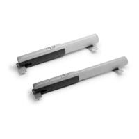
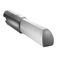
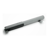
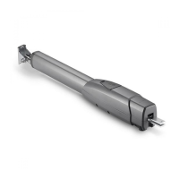
1) Motoriduttore
2) Quadro comando
3) Ricevitore radio
4) Fotocellule di sicurezza
5) Selettore a chiave
6) Antenna
7) Lampeggiatore di movimento
8) Trasmettitore radio
1) Irreversible gear motor
2) Control panel
3) Radio receiver
4) Safety photocells
5) Key-operated selector switch
6) Antenna
7) Flashing light indicating gate movement
8) Radio transmitter
1) Motorreductor irreversible
2) Cuadro de mando
3) Radiorreceptor
4) Fotocélulas de seguridad
5) Selector a llave
6) Antena
7) Lámpara intermitente de movimiento
8) Transmisor
IMPIANTO TIPO
STANDARD INSTALLATION
INSTALACION TIPO
EXTERNAL AUTOMATIC
OPENING SYSTEM FOR
WING GATES WITH
A3000A GEARMOTOR
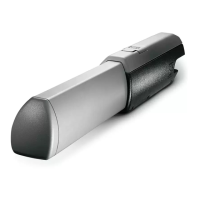
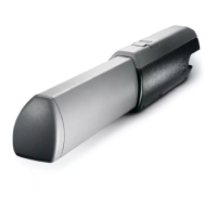
AUTOMAZIONE ESTERNA
PER CANCELLI
A BATTENTE CON
MOTORIDUTTORE A3000A
AUTOMATIZACION
EXTERIOR PARA PUERTAS
BATIENTES CON
MOTORREDUCTOR A3000A
ITALIANO
ENGLISH
ESPAÑOL