
D
Daniel CarterAug 1, 2025
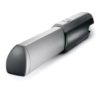
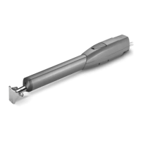
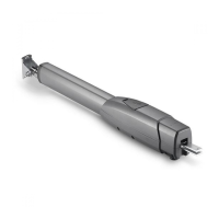
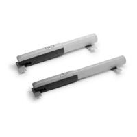
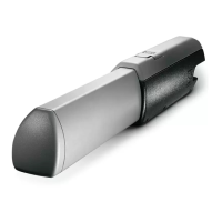
How to troubleshoot a CAME ATI KIT that is not responding?
- SSeth Jacobson Jr.Aug 1, 2025
To troubleshoot a CAME Gate Opener that won't respond to commands, follow these steps: 1. Check the power supply to the control panel. 2. Inspect the control panel fuses. 3. Verify the hard wire link is properly fitted between terminals 1 & 2.