EasyManua.ls Logo

CAME ATI A5000

CAME ATI A5000
12 pages
To Next Page IconTo Next Page
Loading...
Documentazione
Tecnica
49
rev. 4.5
08/2002
©
CAME
CANCELLI
AUTOMATICI
CANCELLI AUTOMATICI
SCHEDA COMANDO
CONTROL BOARD
CARTE DE COMMANDE
STEUERPLATINE
TARJETA DE MANDO
ATI
ITALIANO/ ENGLISH/ ESPAÑOL
119D49-1
SERIE ATI |
ATI SERIES
|
SERIE ATI
1) Motoriduttore
2) Quadro comando
3) Ricevitore radio
4) Fotocellule di sicurezza
5) Selettore a chiave
6) Antenna
7) Lampeggiatore di movimento
8) Trasmettitore radio
1) Irreversible gear motor
2) Control panel
3) Radio receiver
4) Safety photocells
5) Key-operated selector switch
6) Antenna
7) Flashing light indicating gate movement
8) Radio transmitter
1) Motorreductor irreversible
2) Cuadro de mando
3) Radiorreceptor
4) Fotocélulas de seguridad
5) Selector a llave
6) Antena
7) Lámpara intermitente de movimiento
8) Transmisor
Automazione esterna per cancelli a battente
External automatic opening system for wing gates
Automatizacion exterior para puertas batientes
Wiring for microswitches:
5 x 1mm
2
Power wires to motor:
2 x 1,5 mm
2
up to 20 m;
2 x 2,5 mm
2
up to 30 m
Cavi di collegamento microinterruttori:
5 x 1 mm
2
Cavi di alimentazione motore:
2 x 1,5 mm
2
fino a 20 m;
2 x 2,5 mm
2
fino a 30 m.
Cables de conexión microinterruptores:
5 x 1 mm
2
Câbles de alimentación motor:
2 x 1,5 mm
2
hasta 20 m;
2 x 2,5 mm
2
hasta 30 m
A 3024 - A 5024
Impianto tipo
Standard installation
Instalacion tipo
4 x 1,5
2 x 1 - TX
4 x 1
2 x 1,5
3 x 1,5
2 x 1
3 x 1
230 V
4 x 1 - RX
T RG58
4 x 1,5
8
1
1
5
4
3
4
2
4
4
7
6
Question and Answer IconNeed help?

Do you have a question about the CAME ATI A5000 and is the answer not in the manual?

CAME ATI A5000 Specifications

General IconGeneral
Maximum Leaf Length5 m
Maximum Weight500 kg
Power supply230 V AC
Motor voltage230 V AC
Intermittence factor30%
Operating temperature-20°C to +55°C
Protection levelIP54
Safety FeaturesObstacle detection
Control OptionsRemote control

Summary

Technical Characteristics

Product Description

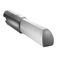
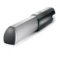
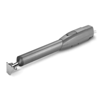
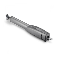
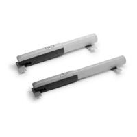
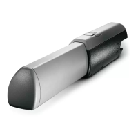
Detailed description of the product's design and features.

Dimensions and Usage Limits

Overall dimensions and application limits for gate wings.

General Control Procedure

Assembly: Initial Steps

Fixing Plate and Bracket Installation

Attaching fixing plates and rear brackets to the pillar and gate wing.

Assembly: Gear Motor Steps

Casing and Rod Removal

Procedures for removing the casing and rod for motor installation.

Gear Motor Installation

Procedures for mounting the gear motor onto the brackets.

Electrical Connections

Connections to Electronic Boards

Wiring diagrams for connecting motors to ZA3/ZA4/ZA5/ZM2 boards.

Connections to Control Panels

Wiring diagrams for connecting motors to ZL14/ZL19 control panels.

Adjusting STOP Microswitch for Opening

Adjusting Deceleration Microswitches

Personalized Key Release

Outside Aperture Installation

Periodic Maintenance

Manufacturers Declaration

Related product manuals