Do you have a question about the CAME FROG SERIES FROG-A 24V and is the answer not in the manual?
Ensures essential checks like power supply, cable protection, and gate structure are done before installation.
Lists the necessary tools and materials required for a safe and compliant installation of the operator.
Provides common malfunctions, their possible causes, and recommended checks or remedies.
The FROG-A 24V is an in-ground operator designed for residential and condominium swing gates, engineered and manufactured by CAME CANCELLI AUTOMATICI S.p.A. in Italy. This product is built to comply with current safety regulations and is certified under ISO 9001:2000 for quality management and ISO 14001 for environmental management.
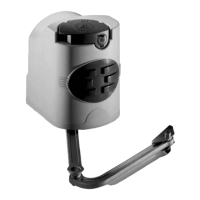
The FROG-A 24V operator is designed to automate swing gates, providing reliable and secure operation. It consists of a foundation box, a release assembly, a gearmotor, and a transmission arm. The zinc-plated press-forged foundation box is intended for underground installation, ensuring a discreet and aesthetically pleasing integration with the gate structure. Inside the foundation box, the release assembly features a customized manual-release key, allowing for manual operation of the gate in case of power outages or emergencies. The gearmotor, housed within a cast aluminum shell, operates an irreversible gear-ratio and an endless screw plus helical crown system, which drives the transmission arm connected to the gate leaf.
The system incorporates brake microswitches and a limit stop adjustment mechanism to precisely control the gate's opening and closing positions. These microswitches read the magnetic field to determine the gate's end-stop positions, allowing for fine-tuning of the stopping points. The limit stop's stopping zone can be adjusted to ensure the gate stops correctly against mechanical stops or obstacles, enhancing safety and preventing damage. The operator is designed for intensive use, making it suitable for high-traffic residential and condominium applications.
The FROG-A 24V is intended for powering swing gates, with specific limits for intensive use and condominiums, accommodating gates up to 400kg in weight and 3.5m in length. Installation must be carried out by expert qualified personnel in full compliance with current regulations to ensure safe and proper operation.
Before installation, several preliminary checks are crucial. These include ensuring a suitable omnipolar cut-off device with contacts more than 3 mm apart and an independent power supply. Proper tubing and conduits for electrical cables are necessary to protect them from mechanical damage and to drain away any water leaks that could cause oxidation. All connections inside the case must have extra insulation to maintain the protective circuit. The gate structure itself must be sturdy, with properly functioning hinges and no friction between moving and non-moving parts. Mechanical stops for both opening and closing are also required.
The installation process involves digging a foundation pit, preparing a drainage system to prevent water accumulation, and carefully positioning the foundation box. The box must be perfectly leveled, with its upper edge approximately 3mm above ground level. Electrical cables should be routed through the designated hole in the box according to command and safety instructions. The rotation pins of the foundation box and the gate attachment lever must be greased and aligned. The gate leaf is then positioned between the upper hinge and the pin lever, which is secured to the gate leaf by welding spots. The gearmotor arm is attached, and the transmission lever is inserted between the motor arm and the box lever. The gate is then electronically shut against the closing end stop, and the adjustment screw is set to ensure proper closing pressure and facilitate re-hooking during the release procedure.
In emergencies, such as power outages, the manual release mechanisms allow the gate to be disengaged and hooked back up for closing. There are three available release models: A4366 with a customized key, A4365 with a tri-lobed key, and A4364 with a lever key. Release operations should only be performed during emergencies and with the power disconnected.
Safety is paramount, and the product must only be used for its intended purpose. Users are advised to avoid working near hinges or other moving parts and to stay clear of the gate's opening/closing arc when it is in motion. Force should not be applied against the operator's movement, as this can lead to dangerous situations. Children should not be allowed to play or loiter near the gate, and remote controls or other command devices should be kept out of their reach to prevent accidental activation. In case of any anomalous behavior, the operator should be stopped immediately.
Periodic maintenance is essential to ensure the longevity and safe operation of the FROG-A 24V. End-users should perform regular checks, including wiping clean the glass surface of the photocells, verifying the proper functioning of safety devices, and removing any obstructions. It is also recommended to check the lubrication state and tightness of the anchoring screws on the operator.
To test the efficiency of safety devices, an object should be moved in front of the photocells while the gate is closing. If the operator reverses motion or stops, the photocells are working correctly. This is the only maintenance procedure that can be carried out with the power source connected. Before performing any other maintenance, the main power must be cut off to prevent accidents. Photocell cleaning should be done with a water-dampened cloth, avoiding solvents or chemical products that could damage the devices. Any strange vibrations or squeaking should prompt lubrication of the joints with grease. It is also important to ensure that no plants obstruct the photocell's beam and that the gate's motion is free of any obstacles.
A periodic maintenance log (every 6 months) is provided for end-users to record dates, notes, and signatures for routine checks. For extraordinary maintenance, repairs, or improvements, specialized technicians must be called upon. An extra-ordinary maintenance log is also included to document these interventions, noting the installer's stamp, operator name, date of job, technician's signature, and requester's signature.
Troubleshooting guidance is provided for common malfunctions. If the gate does not open or close, possible causes include no power, a released gearmotor, run-down remote control batteries, a broken transmitter, a stuck stop button, or stuck opening/closing buttons/key selectors. Remedies involve checking power, calling assistance, replacing batteries, or checking/calling assistance for stuck buttons. If the gate opens but does not close, engaged photocells are a likely cause, requiring a check for cleanliness and proper working order, or calling assistance. If the flasher does not work, a burnt bulb is the probable cause, necessitating a call for assistance.
The product's packaging components (cardboard, plastic, etc.) are classified as solid urban waste and can be easily disposed of through recycling. Product components, including aluminum, plastics, iron, and electrical wires, can be recycled in specific material collection bins or authorized centers. Other components, such as electrical boards and remote control batteries, may contain polluting substances and should be removed and given to qualified service companies for proper disposal. All disposal procedures should comply with local regulations.
| Power Supply | 24V |
|---|---|
| Category | Gate Opener |
| Series | Frog |
| Model | FROG-A |
| Max Leaf Weight | 400 kg |
| Operating Temperature | -20°C to +55°C |
| Protection Rating | IP44 |