EasyManua.ls Logo

CAME FROG-P KIT User Manual

CAME FROG-P KIT
32 pages
To Next Page IconTo Next Page
Page #1 background imageLoading...
Page #1 background image
CAME UNITED KINGDOM LTD
UNIT 3
ORCHARD PARK INDUSTRIAL ESTATE,
TOWN STREET, SANDIACRE,
NOTTINGHAM NG10 5BP
TEL: 0115 921 0430
FAX: 0115 921 0431
INTERNET - www.cameuk.com
E-MAIL - enquiries@cameuk.com
TECHNICAL
HELPLINE
0115 921 0430
FROG KIT
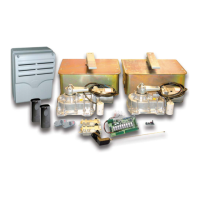
THE FROG-P KIT CONSISTS OF:
2 X UNDERGROUND FOUNDATION CASINGS
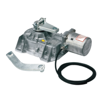
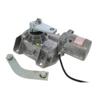
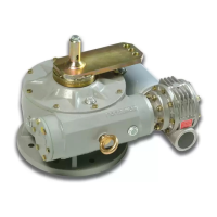
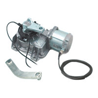
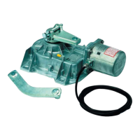
2 X UNDERGROUND GATE MOTORS
1 X CONTROL PANEL
1 X RADIO FREQUENCY CARD
1 X TUNED ANTENNA
2 X REMOTE CONTROL TRANSMITTERS
1 X PAIR SAFETY BEAMS
Installation Instructions
for a “Pair” of gates...

Questions and Answers:

CAME FROG-P KIT Specifications

General IconGeneral
BrandCAME
ModelFROG-P KIT
CategoryGate Opener
LanguageEnglish

Summary

Stage 1 - Civil & Mechanical Section

1.1 - Installation of Foundation Casings

Concreting underground casings with adequate drainage and setting them level.

1.2 - Basic Cable Layout

Diagram of basic cable layout for motors, including power supply and drip-loop concept.

1.3 - Low Voltage Cable Layout

Diagram of low voltage cable layout for accessories like antenna and safety beams.

1.4 - Installing the Motors

Instructions for fitting motors into casings and orienting them correctly relative to gate posts.

1.5 - Hanging the Gates

Guidance on greasing gate pivots and ensuring gates are square and level before welding.

1.6 - Fitting the Gate Lock

Securing the unlocking device to the FROG shoe and operating the release mechanism.

Stage 2 - Wiring & Electrical

2.1 - Fitting the Control Panel in the Casing

Steps to mount the control panel PCB securely into the casing and connect the transformer.

2.2 - Wiring the Motors

Connecting motor wires (blue, brown, black) to the control panel terminal strip for direction and common.

2.3 - Wiring in the Safety Photocells

Wiring instructions for DIR and DOC safety beams to the control panel for safety functions.

2.4 - Inserting the Radio Frequency Card

Procedure for inserting the RF frequency card into the control panel socket while power is off.

2.5 - Wiring in the Tuned Antenna

Diagram showing how to connect the tuned antenna to the control panel's antenna wiring point.

2.6 - Coding the Remote Control

Step-by-step process to program remote controls by transmitting codes to the receiver card.

2.7 - Powering up the Control Panel

Connecting protected mains power to the control panel and ensuring proper earthing.

Stage 3 - Commissioning the Control Panel

3.1 - Initial Wiring & Control Panel Setup

Connecting power, earth, selecting transformer setting, and inserting capacitors.

3.2 - Opening & Closing the Gates

Testing gate operation and verifying motor direction by pulsing terminals.

3.3 - Control Panel Adjustments

Adjusting gate leaf delay, total running time, and sensitivity via trimmers.

3.4 - Automatic Close & Activating Safety Photocells

Enabling automatic closing timer and configuring safety photocells for re-opening.

3.5 - Programming the Remote Controls to the Control Panel

Detailed instructions for storing remote control codes onto the control panel's circuit board.

Troubleshooting Guide

Gate Will Not Respond When Given a Command

Checks for power, fuses, wire links, and capacitors to resolve no-response issues.

Gates Are Open But Will Not Close

Troubleshooting steps for safety beams wiring, power, and hard wire links when gates won't close.

Gate Automatically Opens But Does Not Automatically Close

Addresses issues with incorrect motor wire direction or automatic closing settings.

Gates Will Not Respond to Remote Control Command

Solutions for RF card, programming, code setting, and dipswitch configuration problems.

Technical Information

5.1 - Technical Specification

Provides detailed technical specifications for the gearmotors, including weight, power, and dimensions.

5.2 - Casting Dimensions

Displays the physical dimensions of the underground foundation casing with a diagram.

5.3 - Operating Limits

Lists the maximum gate widths and corresponding maximum gate weights the system supports.

5.4 - Motor Torque Settings

Instructions on how to adjust the motor torque settings using a spade connector on the control board.

Control Panel Description

Overview of the micro-processor controlled electrical cabinet, its features, and protection ratings.

Safety Features and Beam Operation

Explains safety beam functions like re-opening and total stop, and LED indicators.

Connected Accessories

Describes accessories like the "Gate in Motion" lamp and their functionality.

5.6 - ZA4 Wiring Diagram

Illustrates the wiring connections for the ZA4 control panel, including safety beams.

5.7 - Control Panel Adjustments

Detailed explanation of trimmer adjustments for operating time, automatic closing, and leaf delay.

5.8 - Electrical Connections

A comprehensive diagram showing all electrical connections to the control panel terminals.

5.9 - Re-Handing the Frog Motors

Step-by-step instructions for re-orienting the frog motors for left-hand or right-hand gate installations.

6. Contact Information

Related product manuals