
J
Jason RobinsonAug 5, 2025
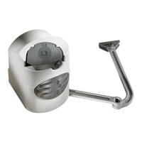
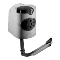
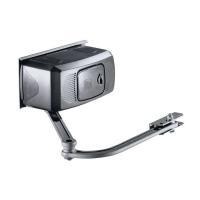
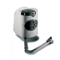
What to do if my CAME F7024N Gate Opener neither opens nor closes?
- KKimberly AlexanderAug 5, 2025
If your CAME Gate Opener is not responding, consider these potential causes: a lack of power, which requires checking the power supply; a discharged transmitter battery, which you can resolve by replacing the batteries. For issues such as a released gearmotor, a faulty transmitter, a stuck or broken stop button, or broken opening/closing buttons or key-switch selector, it's best to call for assistance.