5
The data and information shown in this dialogue may be changed by Came Cancelli Automatici S.p.A. at any time without prior warning.
ENGLISH
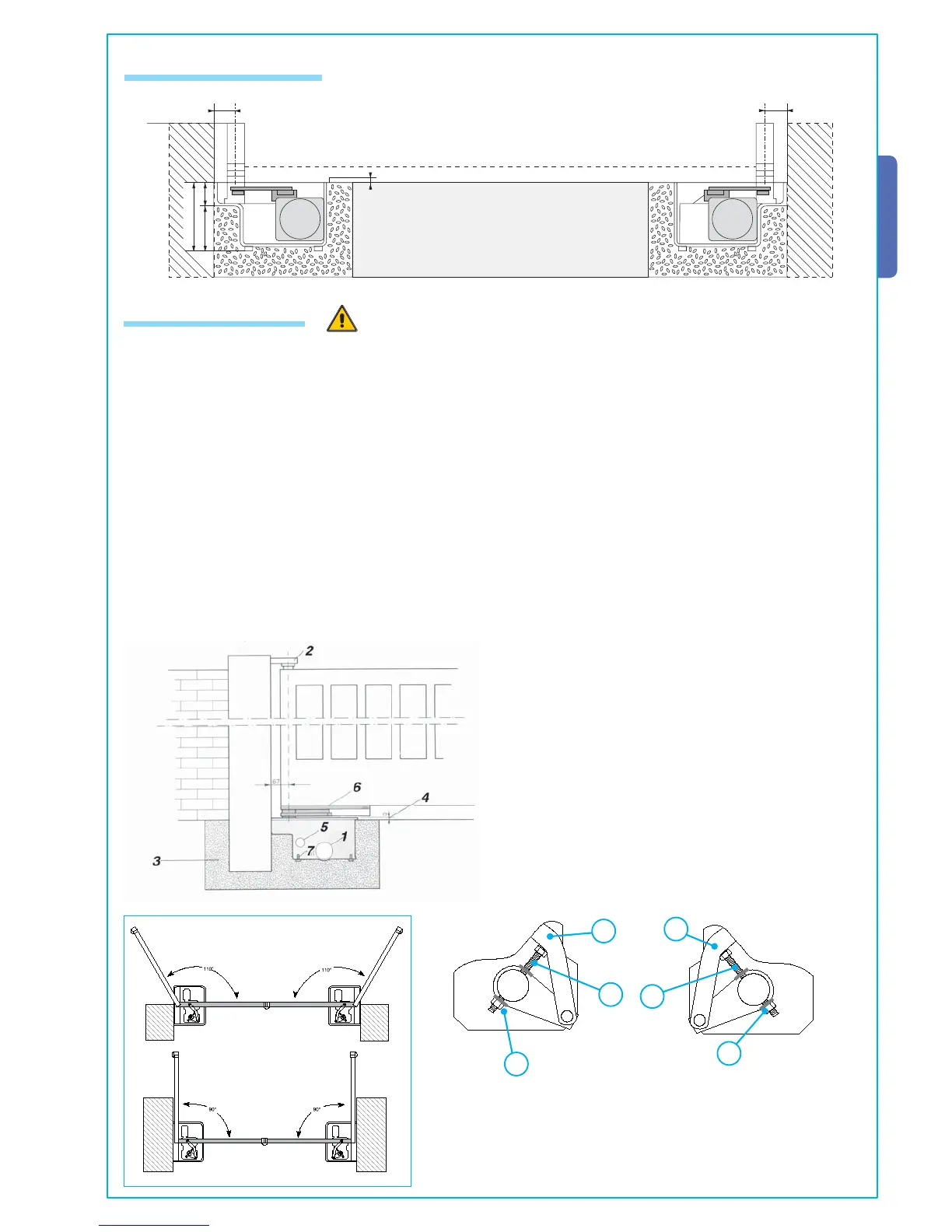
5.5 Assembly diagram
Fig.3
67
67
160
100 60
3
5.6 Installing the unit
- Check the effi ciency of both moving and non-moving parts on the structure that will be supporting the operator;
- Determine, depending on the type of supporting structure and desired opening, the exact position of the motor assembly by
following the standard applications shown;
- Set up a closing end stop and an opening end stop (fi g. 4, p. 5).
- Dig, depending on the size of the assembly, a foundation pit in the chosen spot (Fig. 3);
- Prepare a drainage system in the foundation, to drain away any water leaks which may cause oxidation (fi g 3 – part.1);
- The foundation box makes for quick and easy setting up of the assembly. Place it inside the pit with the pin aligned to the upper
hinge (Fig. 3 – part. 2), sink it into the cement (Fig. 3 – part. 3) making sure it is perfectly levelled and that the upper edge is
3mm above ground level (Fig. 3 part. 4);
- Plan for the route of the electrical cables according to the command and safety instructions using the apposite hole on the box
(Fig. 3 – part. 5);
- Grease the rotation pins of the foundation box and the gate attachment lever; the hinge and pin lever must be aligned;
- Position the gate leaf between the upper hinge and the pin lever; the hinge and pin lever must be aligned;
- Secure the pin lever to the gate leaf, by welding spots 3 to 4 cm apart along the contact surface. Avoid any welding near the
threaded screws (Fig. 3 – Part. 6).
Fig.2
- Screw the M10 x 100 (A) and the M10 (B) bolt onto the gearmotor
arm as shown in fi g. 4-1 (RIGHT HAND installation) and fi g. 4-2
N(LEFT HA D installation);
- Affi x the gearmotor to the foundation box using the threaded pins
and securing it using the provided bolts and washers;
- Insert the (C ) transmission lever between the motor arm and
the box lever and electronically shut the gate against the closing
end stop.
Adjust screw (A) until it touches the (C) transmission lever.
- When testing, adjust the screw so as to allow proper closing
pressure of the gate leaf and allow its re-hooking during the
mechanism’s release procedure.
- Once adjustment is complete, secure the (B) nut.
Fig.4
DX
SX
Fig.4-1
Fig.4-2
A
B
C
C
B
A
SX
DX

 Loading...