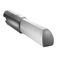
ZA4
2.6 - Wiring in the Safety Photocells
SAFETY BEAMS SHOULD BE FITTED APPROXIMATELY
15 INCHES FROM GROUND LEVEL
CONTROL PANEL
10 11 2 C1
C
NC
RX
10
11
TX
10
11
Fig 13
SAFETY
BEAM
RECEIVER
SAFETY
BEAM
TRANSMITTER
IF FITTING A SECOND ARC LINE SET OF SAFETY BEAMS THEN C & NC MUST BE WIRED IN “SERIES”
2.7 - Inserting the Radio Frequency Card
INSERT THE RADIO FREQUENCY
CARD INTO THE SMALL SOCKET
ON THE CONTROL PANEL
(ENSURE THAT THE POWER IS
TURNED OFF TO THE CONTROL
PANEL BEFORE INSERTING THE
FREQUENCY CARD)
ANTENNA
WIRING
POINT
Fig 14
NC
C
14

 Loading...